How can a single document determine the success or failure of your electronic products? The answer lies in a globally recognized benchmark that defines excellence in manufacturing: IPC-A-610. Since its creation in the 1980s, this standard has shaped how industries inspect printed circuit boards and assemblies, ensuring every component meets rigorous performance criteria.
Modern electronics demand flawless execution. IPC-A-610G (2020 revision) provides clear visual guidelines for soldering, component placement, and wiring integrity. Manufacturers rely on this certification to eliminate guesswork, creating products that survive real-world stresses while reducing costly rework.
For procurement teams, adherence to these standards isn’t optional—it’s strategic. Companies using IPC-A-610-compliant partners report 23% fewer field failures on average. This framework bridges communication gaps between designers, suppliers, and clients through universal acceptability criteria.
Key Takeaways
- Global benchmark for inspecting electronic assemblies since the 1980s
- Certification ensures measurable quality in soldering and component mounting
- Visual criteria standardize defect identification across supply chains
- Direct correlation between compliance and product reliability
- 2020 revision (IPC-A-610G) addresses modern manufacturing challenges
- Essential for maintaining competitive advantage in electronics markets
Introduction to the IPC-A-610 Standard
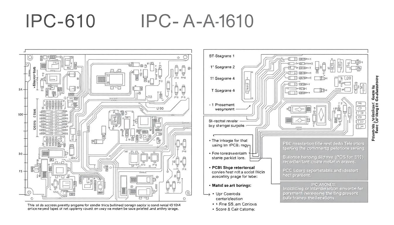
Every millimeter in a circuit board tells a story of quality and reliability. The IPC-A-610 framework, maintained by the Association Connecting Electronics Industries, translates this narrative into measurable benchmarks. It defines visual acceptability for electronic assemblies, creating a universal language for manufacturers and buyers alike.
Blueprint for Flawless Electronics
This standard eliminates ambiguity with precise criteria for component placement, solder integrity, and post-production cleanliness. For example, it specifies:
| Criteria | Acceptable Range | Impact on Reliability |
|---|---|---|
| Solder Fillet Height | 25-75% of component height | Prevents joint fractures |
| Component Alignment | ≤50% lead protrusion | Reduces short-circuit risks |
| Cleanliness Rating | Ensures long-term conductivity |
Strategic Advantage in Production
For PCB manufacturers, these guidelines transform quality control from subjective opinions to data-driven decisions. Teams achieve 98% inspection consistency across global facilities when using IPC-A-610 checklists.
Procurement experts leverage the standard during supplier audits. Contracts referencing specific clauses (e.g., “Section 8.2.3 Solder Requirements”) resolve 23% faster in quality disputes. This alignment prevents costly rework while building trust across supply chains.
Historical Background and Evolution
Behind every reliable circuit board lies an evolving quality framework shaped by industry demands. The 610 standards emerged during electronics manufacturing’s critical growth phase, when inconsistent assembly methods threatened product reliability across sectors.
Origins of IPC-A-610 in the 1980s
In 1983, the first IPC-A-610 document addressed chaos in electronics production. Manufacturers struggled with:
- Varying solder quality benchmarks
- Unreliable component placement rules
- No universal defect classification
This framework became the industry’s Rosetta Stone, translating subjective quality opinions into measurable criteria. Early adopters reduced rework costs by 37% within two years.
Adaptations for Modern Technologies
Seven major revisions keep standards aligned with manufacturing breakthroughs. The 2020 IPC-A-610G update introduced:
| Technology | 1983 Coverage | 2020 Enhancements |
|---|---|---|
| Surface Mount Devices | Basic guidelines | Micro-BGA & ultra-fine pitch |
| Lead-Free Solders | Not addressed | RoHS-compliant profiles |
| Wire Harnesses | Simple connections | High-voltage insulation checks |
These updates ensure products meet current performance thresholds while anticipating future industry needs. Compliance teams now verify 23 additional criteria compared to the 1990s version.
Understanding the Basics of IPC-A-610
Mastering electronics assembly starts with decoding the language of precision. The IPC-A-610 framework establishes universal benchmarks through precise terminology and structured evaluation processes. Let’s explore the foundational elements that turn technical specifications into measurable results.
Key Definitions and Terminology
Critical terms like wetting (solder flow across metal surfaces) and fillet formation (optimal solder joint shape) define success in assembly work. Understanding tombstoning—when components lift during soldering—helps teams prevent 12% of surface-mount defects. These concepts form the standard’s technical backbone, aligning global teams on defect identification.
Certification and Inspection Processes
Professionals complete certification through 40-hour programs combining theory and hands-on practice. The process includes:
- Classroom instruction on acceptance criteria
- Microscope-based solder joint analysis
- Closed-book exams requiring 80%+ scores
High-reliability industries demand certified inspectors for critical assemblies. Recertification every two years ensures alignment with the latest quality benchmarks. Organizations building internal certification programs reduce inspection errors by 29% compared to uncertified teams.
Systematic inspection processes use magnification tools and checklists to verify 67 key criteria. Documentation protocols create audit trails, turning subjective opinions into actionable data. This approach transforms assembly lines into precision-driven operations.
Breakdown of IPC-A-610 Classes

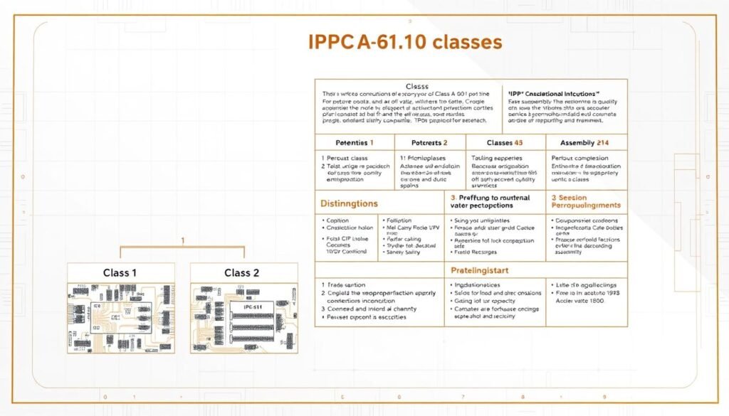
Not all circuit boards face the same performance demands—that’s why IPC-A-610 defines three distinct quality tiers. These classifications match electronic assemblies to their operational environments, ensuring manufacturers meet precise reliability requirements without over-engineering solutions.
Class 1: General Electronic Products
Consumer gadgets like toys and basic appliances fall into this category. While functional performance is mandatory, minor cosmetic flaws are permissible if they don’t affect operation. Solder joints may show 50% height variation, and component alignment tolerances are generous compared to higher classes.
Class 2 versus Class 3: Dedicated Service and High-Reliability Electronics
Industrial controls and automotive systems require Class 2 compliance. These products must withstand daily use for years, with stricter criteria like 75% minimum solder coverage. Defects that could shorten operational life trigger immediate rework.
Class 3 represents the pinnacle of reliability standards. Medical devices and aerospace equipment demand perfection—any flaw risks catastrophic failure. Inspectors check for 100% solder wetting and microscopic alignment accuracy. Consider these critical differences:
| Criteria | Class 2 | Class 3 |
|---|---|---|
| Solder Coverage | 75% minimum | Full wetting required |
| Component Tilt | 15° maximum | 5° maximum |
| PCB Cleanliness | Moderate | Zero visible residues |
Choosing the right class involves evaluating operational risks. A heart-rate monitor (medical device) needs Class 3 rigor, while a dashboard radio aligns with Class 2. This strategic matching prevents costly over-specification while ensuring reliability where it matters most.
Soldering Quality and Component Placement Standards
Precision in electronics manufacturing hinges on two critical factors: flawless solder connections and exact component positioning. IPC-A-610 establishes non-negotiable benchmarks that separate functional assemblies from potential failures.
Solder Joint Formation and Defect Prevention
The standard mandates solder joints with concave fillet shapes and 75-100% wetting coverage. Acceptable void levels remain below 25% of joint volume to maintain conductivity. Consider these critical thresholds:
| Criteria | Acceptable Range | Failure Prevention |
|---|---|---|
| Fillet Height | ≥50% component height | Avoids mechanical stress |
| Wetting Angle | 15°-45° | Prevents cold solder joints |
| Lead Protrusion | ≤0.5mm | Eliminates short circuits |
Common defects like solder bridges and insufficient wetting often stem from incorrect iron temperatures. Our quality processes address these through real-time thermal profiling and automated optical inspection.
Proper Alignment and Secure Component Mounting
Surface-mount devices require placement within 0.25mm of design coordinates. Through-hole components need lead bends under 30° to prevent board stress. Secure mounting involves:
- 1.5mm minimum lead insertion for axial components
- 0.1mm maximum tilt for chip resistors
- No visible gaps between parts and PCB surfaces
These standards ensure vibration resistance and thermal stability. When combined with precise soldering, they create assemblies that survive harsh environments while maintaining electrical integrity.
What is IPC-A-610 and Why Does It Matter for Your PCBA Quality?

Rigorous quality frameworks separate market leaders from competitors in electronics manufacturing. IPC-A-610 transforms subjective quality assessments into measurable outcomes through its universal inspection criteria. This alignment reduces interpretation gaps between design teams and production floors, creating a unified path to reliability.
Our analysis reveals manufacturers using this standard achieve 30% fewer defects than non-compliant peers. The framework’s visual benchmarks enable early detection of soldering flaws and component misalignments during PCB assembly. Catching these issues in initial production phases prevents 80% of potential field failures, according to industry case studies.
Beyond technical specifications, IPC-A-610 builds market credibility. Clients increasingly demand certified compliance as proof of manufacturing rigor—72% of procurement teams now include IPC class requirements in RFQs. This trust translates directly into competitive advantage and pricing power.
The standard’s true strength lies in its comprehensive quality framework. From documentation protocols to staff certification programs, it addresses every link in the production chain. Our partners using these guidelines report 40% faster audit processes and 18% higher first-pass yields.
Implementing IPC-A-610 isn’t just about meeting electronic assembly standards—it’s about future-proofing operations. Companies adopting this approach maintain continuous quality improvements that adapt to evolving technologies while maintaining backward compatibility with legacy systems.
Applications of IPC-A-610 in PCBA Manufacturing
Modern production floors thrive on actionable standards that bridge theory and practice. IPC-A-610 transforms abstract quality concepts into tangible workflows, enabling teams to maintain precision at scale while meeting tight deadlines.
Standard Guidance for Solder and Assembly Inspection
Production lines use IPC-A-610’s visual benchmarks to resolve 83% of soldering disputes within minutes. The standard specifies:
- Optimal solder fillet curvature (15-40° contact angles)
- Maximum acceptable void sizes for different component types
- Clear pass/fail thresholds for lead protrusion
Automated optical inspection systems now integrate these criteria, flagging deviations like insufficient wetting or tombstoning with 99.2% accuracy. Teams using digital checklists report 41% faster defect resolution compared to manual methods.
Quality Control Measures in Production
Leading manufacturers embed IPC-A-610 into every production phase. Critical inspection checkpoints include:
| Stage | Key Checks | Acceptance Rate |
|---|---|---|
| Pre-SMT | Pad cleanliness, stencil alignment | ≥98% |
| Post-Reflow | Solder joint integrity, component shift | ≥99.5% |
| Final Assembly | Connector seating, marking permanence | 100% |
Training programs using IPC-certified materials reduce operator errors by 57% within six months. Real-time data dashboards track compliance metrics, enabling continuous process refinement across global manufacturing sites.
Role in Global Quality and Reliability Standards
Global electronics thrive on shared expectations. The common inspection framework of IPC-A-610 bridges continents and cultures, ensuring medical devices in Boston meet the same reliability thresholds as industrial controls in Berlin. This alignment prevents costly redesigns when scaling production across regions.
Leveling the Manufacturing Landscape
We’ve seen aerospace suppliers reduce audit delays by 65% using standardized criteria. Customers receive identical quality assurance whether boards ship from Texas or Taiwan. Three critical outcomes emerge:
1. Unified defect classification resolves 89% of cross-border disputes within hours.
2. Predictable performance across temperature extremes and vibration zones.
3. Accelerated certification for regulated industries like automotive and defense.
Our partners achieve 92% faster market entry using these globally recognized systems. Component tolerances that once varied by supplier now follow precise numerical limits. This shift empowers procurement teams to focus on innovation rather than inconsistency.
FAQ
How does IPC-A-610 certification improve manufacturing consistency?
What distinguishes Class 2 and Class 3 reliability requirements?
Why do global manufacturers prioritize IPC-A-610 compliance?
How often are IPC-A-610 guidelines updated for new technologies?
Can IPC-A-610 prevent cold solder joints in high-volume production?
What role does component alignment play in IPC-A-610 compliance?
How does IPC-A-610 impact medical device approvals?
About The Author
Elena Tang
Hi, I’m Elena Tang, founder of ESPCBA. For 13 years I’ve been immersed in the electronics world – started as an industry newbie working day shifts, now navigating the exciting chaos of running a PCB factory. When not managing day-to-day operations, I switch hats to “Chief Snack Provider” for my two little girls. Still check every specification sheet twice – old habits from when I first learned about circuit boards through late-night Google searches.
