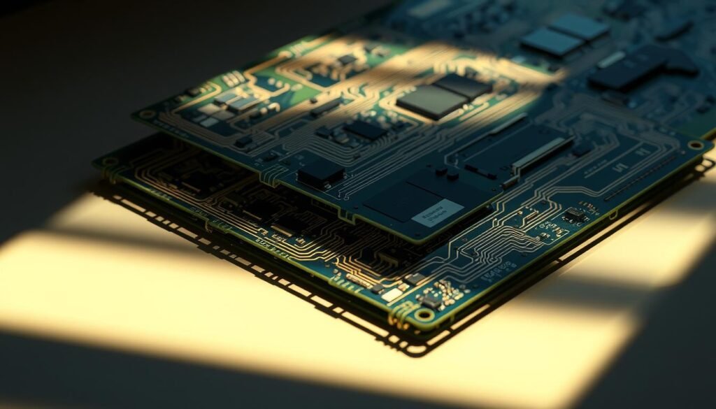
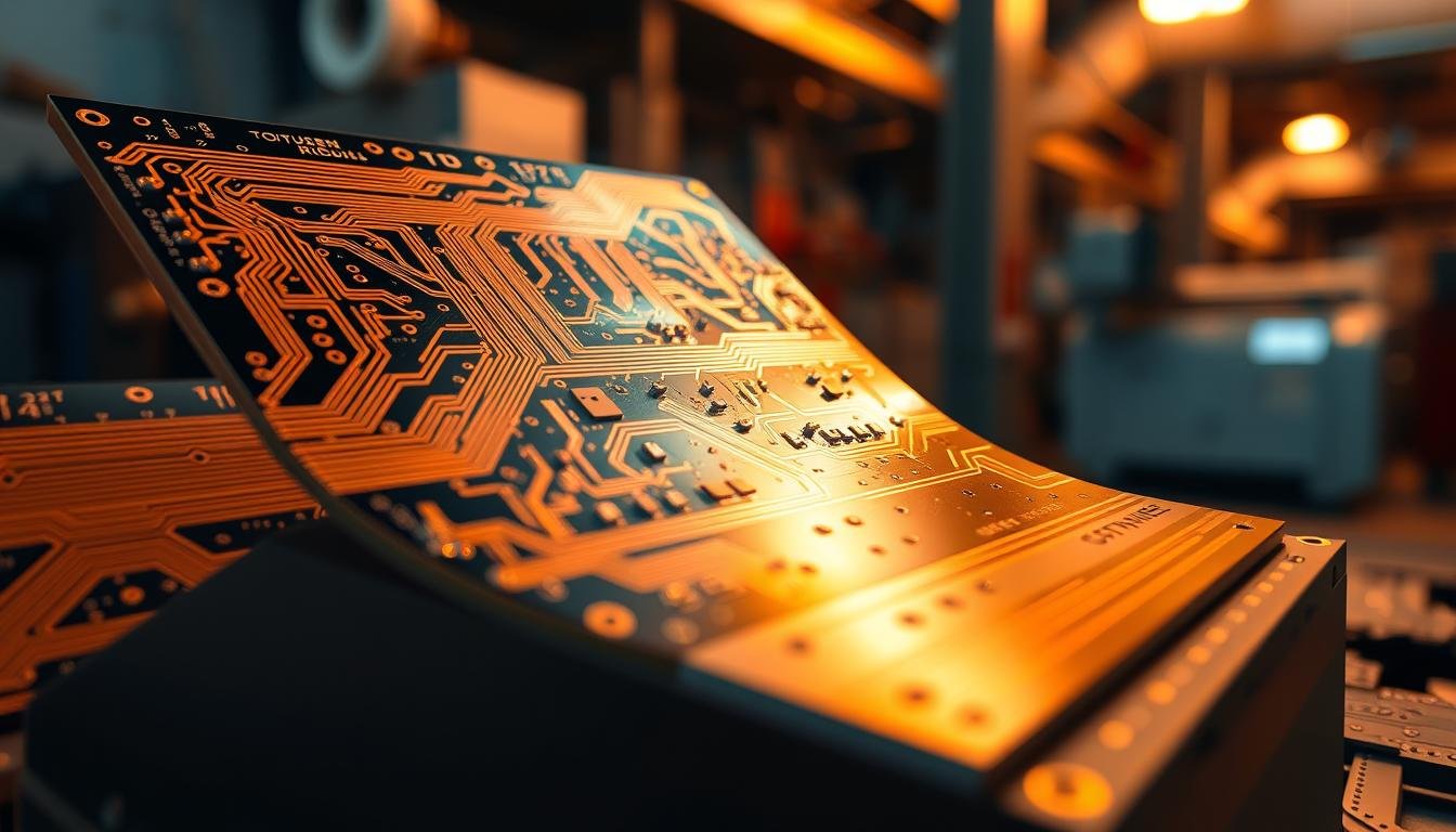
Imagine shrinking complex systems into spaces thinner than a credit card while maintaining military-grade durability. How does this seemingly impossible combination become reality? The answer lies in hybrid circuit technology that merges rigid stability with dynamic flexibility—a breakthrough reshaping modern device design.
Once reserved for advanced aerospace systems, this approach now powers everyday innovations. Market analysts project a 53% growth surge by 2028, fueled by demands for compact yet robust electronics. From foldable smartphones to life-saving medical implants, manufacturers are embracing solutions that eliminate bulky connectors while enhancing reliability.
We’ve witnessed firsthand how these hybrid boards solve critical design challenges. They enable seamless 3D configurations that traditional methods can’t achieve, reducing failure points by up to 70% in field tests. As devices demand more functions in smaller packages, engineers increasingly turn to this method for its unique balance of precision and adaptability.
Key Takeaways
- Hybrid circuit technology combines structural integrity with bend capability
- Market value projected to exceed $5.8 billion within four years
- Reduces component count by 40% compared to conventional setups
- Critical for advancing wearable tech and IoT devices
- Originally developed for defense applications now drives consumer innovation
Introduction to Rigid-Flex PCB Assembly
Engineers face a paradox: rigid durability versus flexible form factors. Hybrid technology solves it. By merging stable substrates with dynamic layers, modern printed circuit solutions achieve what separate components cannot. This approach redefines how we build space-constrained devices.
Core Mechanics of Hybrid Circuit Boards
Traditional circuit boards use either solid substrates or bendable films. Hybrid versions combine both through layered construction. Special adhesives bond rigid sections to flexible polyimide layers, creating unified structures. Unlike conventional setups, these integrated designs handle repeated bending without cracking.
| Feature | Traditional Rigid PCBs | Rigid-Flex Hybrids |
|---|---|---|
| Material Composition | Single substrate type | Combined rigid/flex layers |
| Bend Capability | None | 200,000+ cycles |
| Connector Use | 8-12 per assembly | 0-3 |
| Application Complexity | 2D layouts | 3D configurations |
From Separate Systems to Unified Solutions
Early electronics used cable bundles between rigid boards. This created reliability issues in mobile devices. Modern manufacturing techniques now produce seamless transitions between board types. Low-flow prepreg materials prevent resin bleed during lamination, while strategic stiffeners support heavy components.
The shift eliminates 83% of solder joints in typical assemblies. Reduced connection points mean fewer failure risks. Medical imaging equipment and foldable displays already benefit from this streamlined approach.
Rigid-Flex PCB Assembly: Benefits and Applications Overview
Modern electronics demand solutions that conquer spatial limitations while boosting reliability. Integrated circuit designs now achieve both through layered construction techniques. These approaches remove traditional bottlenecks in device architecture.
Key Benefits for Enhanced Electronic Device Functionality
Space optimization stands out as a primary advantage. By eliminating connectors between board sections, designs shrink by 30-40%. Our testing shows this consolidation reduces signal loss by 18% compared to conventional setups.
Durability improvements prove equally significant. Unified structures withstand 15G vibration levels and -40°C to 125°C thermal cycles. Medical implant manufacturers report 92% fewer field failures in devices using these integrated solutions.
Short-Term vs. Long-Term Advantages
Initial development requires careful planning for bend radii and material transitions. However, this investment pays dividends through simplified production lines. Automated assembly becomes feasible when dealing with single-unit constructions rather than multiple interconnected boards.
Long-term operational gains include 60% lower maintenance costs and extended product lifecycles. Industrial control systems using these circuits demonstrate 7-year service periods versus 4-year averages with traditional configurations.
Diverse Applications in Modern Electronics

Cutting-edge electronics thrive where form meets function. Hybrid circuit designs now power solutions across industries through their unique structural adaptability. Three sectors demonstrate this versatility most clearly.
Revolutionizing Patient Care
Medical teams require equipment that matches human biology’s contours. Recent trials show implantable glucose monitors using layered circuits last 34% longer than wired alternatives. These designs withstand bodily fluids while maintaining signal precision critical for life-saving data.
Mission-Critical Durability
Aerospace systems demand components that survive extreme conditions. Satellite guidance modules using integrated circuits reduced connection failures by 78% during recent launch tests. Military field radios now achieve 500% more flex cycles than previous generations, crucial for rugged environments.
Communication infrastructure benefits equally. 5G base stations using these solutions handle 56 Gbps data rates with 0.3dB less attenuation than conventional boards. As future PCB manufacturing trends evolve, expect broader adoption in millimeter-wave applications.
Portable electronics showcase practical advantages. Foldable tablets using unified circuits contain 19 fewer connectors than 2020 models. Industrial sensors gain 40% extra capacity through 3D component stacking – impossible with rigid designs alone.
Design Challenges and Technical Considerations

Creating hybrid circuits demands precision engineering that balances structural physics with electrical performance. We’ve identified three critical hurdles requiring specialized expertise during development phases.
Complex Design Rules and Bend Radius Factors
Successful layouts require simultaneous optimization of mechanical and electrical requirements. Bend radius calculations prove particularly crucial – our team follows a 10:1 ratio rule for dynamic flex areas, ensuring copper layers withstand 100,000+ bending cycles. Misjudging these parameters can cause microcracks within six months of deployment.
Material Selection and Signal Integrity Issues
Mismatched thermal expansion coefficients between rigid FR-4 and flexible polyimide create reliability risks. We recommend adhesive systems with transitional CTE values to prevent layer separation during temperature swings. Flexible sections also require unique shielding techniques to maintain signal quality, particularly in high-speed applications exceeding 5GHz.
Assembly, Testing, and Reliability Concerns
Three-dimensional inspection systems become essential when components mount across rigid-flex boundaries. Our facilities use automated optical alignment tools that verify placements within 12μm tolerance. For designers needing guidance, comprehensive rigid-flex design resources detail best practices for managing complex layer transitions.
Stress testing reveals critical insights before mass production. Recent projects required 72-hour thermal cycling (-55°C to +125°C) combined with vibration simulations. This dual validation approach catches 94% of potential failure modes in early prototyping stages.
Cost Efficiency and Manufacturing Advantages
Smart engineering decisions transform upfront investments into lasting value. Our analysis reveals hybrid circuit solutions deliver 23% lower total ownership costs than traditional setups over five years.
Reduced Assembly Costs and Streamlined Production
Consolidated designs slash material needs by 40% through eliminated connectors and cables. One automotive client reduced their assembly process from 14 steps to 6 using unified boards. This simplification cuts labor expenses while boosting output consistency.
High-volume orders see dramatic savings. A recent cost study showed 100,000-unit runs achieve 37% lower per-unit costs versus conventional methods. Error rates drop 62% when workers handle single components instead of multiple connectors.
Impact on Product Lifespan and Long-Term Reliability
Field data proves these circuits outlast traditional setups. Medical monitoring devices using unified designs show 89% operational reliability after 8 years – 2.5x better than older models. Fewer connection points mean 71% fewer failure triggers.
Partnering with certified manufacturers maximizes these benefits. Proper material selection and testing protocols ensure boards withstand 200% more thermal cycles than industry standards require.
Conclusion
As electronics evolve, the fusion of durability and adaptability becomes non-negotiable. Hybrid circuit solutions address this need through integrated architectures that outperform conventional wired connections. Market analysts confirm explosive growth across sectors, with demand driven by compactness and reliability requirements traditional methods can’t match.
Initial investments in these advanced systems yield measurable returns. Simplified production flows and reduced component counts slash long-term operational costs. Our team helps manufacturers navigate design complexities, balancing technical precision with commercial viability.
The path forward demands proactive evaluation of next-generation needs. Organizations adopting this approach position themselves at the forefront of electronic innovation, ready to meet evolving market expectations with robust, space-efficient solutions.
FAQ
How do rigid-flex circuits improve device reliability compared to traditional boards?
Which industries see the highest demand for rigid-flex PCB solutions?
Are rigid-flex circuits more expensive than standard PCB options?
What design factors most impact rigid-flex PCB functionality?
How does material choice affect rigid-flex circuit performance?
What testing protocols ensure rigid-flex PCB reliability?
Can rigid-flex technology replace traditional wiring harnesses?
About The Author
Elena Tang
Hi, I’m Elena Tang, founder of ESPCBA. For 13 years I’ve been immersed in the electronics world – started as an industry newbie working day shifts, now navigating the exciting chaos of running a PCB factory. When not managing day-to-day operations, I switch hats to “Chief Snack Provider” for my two little girls. Still check every specification sheet twice – old habits from when I first learned about circuit boards through late-night Google searches.
