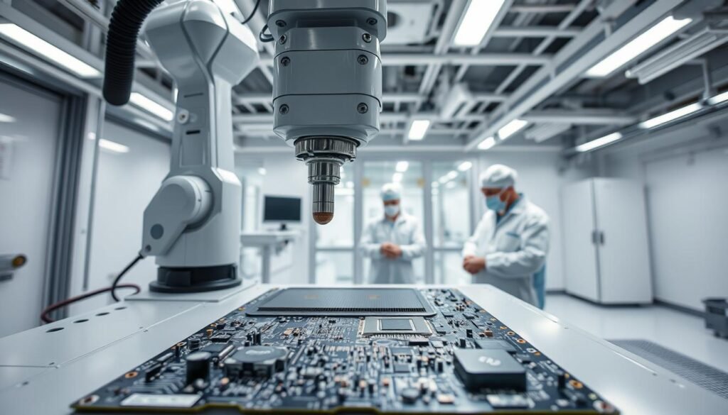
Modern aviation and space systems require precision-engineered circuit boards that withstand extreme operational demands. At the core of these systems lie assemblies built to IPC-A-610 Class 3 standards – the benchmark for high-reliability electronics. These components face relentless stress from altitude shifts, thermal cycling, and mechanical vibration during service.
Our methodology integrates advanced manufacturing stages with specialized protective measures. From solder paste inspection to precision coating solutions, every phase prioritizes longevity under harsh conditions. Plasma treatment ensures surface readiness, while automated optical inspection guarantees microscopic accuracy.
Three critical factors drive our approach:
- Adherence to aviation-grade material specifications
- Multi-stage quality verification protocols
- Environment-specific protection strategies
We maintain zero tolerance for particulate contamination – a stance reinforced through cleanroom protocols and ionic purity testing. This vigilance extends to coating thickness control, where sub-micron accuracy prevents electrical leakage in low-pressure environments.
Key Takeaways
- IPC Class 3A represents the highest reliability tier for flight systems
- Multi-environment stress testing validates component durability
- Automated inspection detects defects invisible to human operators
- Surface preparation directly impacts protective coating efficacy
- Process validation occurs at 14 checkpoints minimum
Overview of Aerospace PCBAs and Environmental Challenges
Aviation electronics face survival tests daily that ground-based systems never encounter. Circuit boards in flight systems endure simultaneous assaults from multiple environmental threats while maintaining flawless operation.
Hostile Operational Realities
Flight electronics confront unique stressors across three domains:
| Environmental Factor | Typical Range | Impact on PCBAs |
|---|---|---|
| Temperature | -65°F to 257°F | Material expansion/contraction |
| Pressure | Sea level to vacuum | Outgassing risks |
| Vibration | 10-2000 Hz | Solder joint fatigue |
| Humidity | 0-100% RH | Corrosion potential |
Mission-Critical Reliability Needs
We design protection strategies recognizing that aviation systems can’t tolerate single-point failures. Our process controls address:
- 20-year minimum operational lifespan requirements
- Zero-maintenance operation in inaccessible locations
- Simultaneous exposure to multiple stressors
Every decision in material selection and process design ties directly to preventing catastrophic outcomes. Through accelerated life testing, we verify assemblies withstand 3x their intended service conditions.
Essential Cleaning Procedures for Aerospace Assemblies

Reliable protection begins with immaculate surfaces. Our team treats PCB preparation as mission-critical, knowing even nanoscale residues threaten performance. Through rigorous testing, we’ve developed protocols that exceed aviation-grade cleanliness standards.
Decontamination Methods and Best Practices
We combat contaminants through multi-stage purification. Plasma technology removes organic residues at molecular levels without damaging delicate components. For ionic contaminants, de-ionized water systems achieve 18.2 MΩ·cm purity – 100x cleaner than standard rinse water.
| Method | Process Details | Key Benefits |
|---|---|---|
| Plasma Cleaning | Removes 99.9% organic residues | No harsh solvents required |
| De-ionized Water | 3-stage filtration system | Prevents electrochemical migration |
| Ultrasonic | 40 kHz frequency | Cleans complex geometries |
Role of Plasma and De-ionized Water Cleaning
Plasma treatment creates optimal surface energy (≥38 dynes/cm) for coating adhesion. We validate results using Dyne pens before moving boards to controlled environments. Anti-static gloves and nitrogen-purged chambers prevent recontamination during transfer.
Our final verification stage uses ultraviolet inspection to detect invisible residues. This ensures every PCB meets IPC J-STD-001 Class 3 requirements before protective applications begin.
Cleaning and Conformal Coating Processes for Class 3A Aerospace Assemblies

Mission-critical electronics demand integrated manufacturing solutions that merge surface preparation with advanced protection techniques. Our approach transforms raw boards into fortified systems through synchronized stages, each timed to prevent performance-compromising gaps.
Sequenced Manufacturing Protocol
We initiate protection workflows immediately after solder validation. Nitrogen-enriched reflow chambers create oxidation-free joints, while inline X-ray verification ensures structural integrity. Automated dispensers apply coatings within 90 minutes of final cleaning – a window that prevents airborne contaminants from settling.
Key stages include:
- Viscosity-controlled material deposition
- Humidity-locked application environments (45-55% RH)
- Infrared curing at 70°C ±2° tolerance
Temporal Precision Requirements
Three thermal shock cycles at 288℃ validate coating adhesion under extreme stress. Nozzle cleaning intervals prevent flow rate deviations exceeding 0.5μl/sec. We track 18 environmental parameters in real-time, including:
| Parameter | Control Range | Measurement Frequency |
|---|---|---|
| Material Temp | 22°C ±0.5° | Every 15 sec |
| Cure Duration | 8.5-9.5 min | Per board |
| Layer Thickness | 25-75μm | 5-point inspection |
This regimented process eliminates variables that could degrade protective performance. Digital records document each critical phase, creating an auditable trail from raw materials to flight-ready assemblies.
Techniques and Materials for Effective Conformal Coating
Protective material selection forms the foundation of durable flight electronics. We evaluate resin properties against operational demands to ensure coatings perform under thermal extremes and chemical exposure. Three primary formulations dominate aviation-grade solutions.
Resin Performance Characteristics
Each coating type offers distinct advantages for specific scenarios:
| Material | Best For | Limitations |
|---|---|---|
| Acrylic | Cost-sensitive projects Easy repairs |
Weak solvent resistance |
| Silicone | Thermal cycling Flexible substrates |
Difficult removal |
| Urethane | Fuel vapor environments Abrasion resistance |
Long cure times |
“The right coating adds years to component lifespan without adding unnecessary complexity,” notes our lead materials engineer. This philosophy guides our formulation recommendations.
Precision Application Systems
Modern spray technologies achieve micron-level accuracy across complex board geometries. We deploy:
- Robotic nozzles for selective coverage
- Programmable systems for batch consistency
- Dipping tanks for high-volume throughput
Automated systems maintain 97% material utilization rates through real-time viscosity monitoring. Our quality checks verify coating integrity across 12 environmental parameters, including thermal shock resistance and dielectric stability.
For mission-critical units, we combine urethane resistance properties with robotic application methods. This pairing withstands jet fuel exposure while maintaining precise thickness tolerances (±5μm).
R&D Considerations in Aerospace PCBA Design
Engineering electronics for extreme environments demands material innovation and electromagnetic precision. Our R&D team bridges substrate science with signal integrity, creating boards that survive orbital radiation and atmospheric re-entry.
Material Selection and High-Performance Substrates
We specify laminates based on three criteria: thermal stability, dielectric consistency, and mechanical resilience. Rogers RO4000 series dominates RF applications with near-zero moisture absorption. For millimeter-wave systems, RT/duroid substrates maintain signal clarity at 77 GHz.
Key considerations for MIL-spec components:
- CTE matching between substrates and copper layers
- Glass transition temperatures exceeding 280°C
- Peel strength retention after thermal cycling
EMC Considerations and Routing Guidelines
Aerospace PCB design battles electromagnetic interference on two fronts: internal noise and external radiation. Our strategies include:
| Challenge | Solution | Benefit |
|---|---|---|
| Signal coupling | 3W rule for trace spacing | Reduces crosstalk by 72% |
| Ground loops | Multi-point star grounding | Cuts EMI by 40dB |
| Thermal noise | Buried capacitance layers | Stabilizes power delivery |
“Routing density isn’t about cramming traces – it’s about intelligent separation,” explains our lead designer. We isolate analog/digital domains using moated ground planes, while maintaining 85Ω impedance control across differential pairs.
Final validation includes near-field scans and thermal imaging, ensuring designs meet both performance thresholds and manufacturability requirements. This dual focus allows seamless integration with coating processes without compromising electrical integrity.
Quality Certifications and Industry Standards
Certifications form the backbone of trust in high-stakes electronics production. Our team maintains three pillars of validation – international quality systems, aviation-specific protocols, and specialized process accreditations. These frameworks ensure every component meets life-or-death reliability thresholds.
Foundational Quality Benchmarks
ISO 9001:2015 anchors our quality management system, with AS9100D extending these principles for aviation-grade manufacturing. Nadcap accreditation elevates critical processes – including surface preparation – beyond standard industry requirements. We renew these credentials annually through unannounced audits.
Specialized Compliance Protocols
Every assembly undergoes 47-point verification against IPC-CC-830B and MIL-I-46058C specifications. Our testing labs simulate orbital radiation exposure and fuel vapor corrosion to validate coating integrity. Digital records track 112 quality parameters from material sourcing to final inspection.
Global projects benefit from our dual compliance with GB/T 39342-2020 and GOST-R certifications. Supplier qualification programs ensure components meet aerospace thermal stability needs before entering production. This multi-layered approach delivers traceability that satisfies even NASA-level documentation requirements.
FAQ
How do aerospace environmental conditions impact conformal coating selection?
What cleaning validation methods ensure Class 3A assembly reliability?
Why does coating thickness directly affect PCB performance in aerospace systems?
How do AS9100 and Nadcap certifications impact conformal coating processes?
What design factors influence cleaning effectiveness for RF aerospace circuits?
When should urethane coatings replace silicone in avionics applications?
About The Author
Elena Tang
Hi, I’m Elena Tang, founder of ESPCBA. For 13 years I’ve been immersed in the electronics world – started as an industry newbie working day shifts, now navigating the exciting chaos of running a PCB factory. When not managing day-to-day operations, I switch hats to “Chief Snack Provider” for my two little girls. Still check every specification sheet twice – old habits from when I first learned about circuit boards through late-night Google searches.
