Are you aware of the impact that component packaging has on the efficiency and cost-effectiveness of your SMT manufacturing processes?
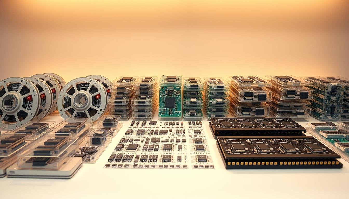
Choosing the right packaging format for components is as crucial as the parts themselves in electronics manufacturing. The packaging method affects pick-and-place efficiency, component protection, and inventory costs. We will explore the critical role of component packaging in SMT assembly processes, focusing on reels, trays, and cut tape.
By understanding the nuances of different packaging options, manufacturers can optimize their assembly processes, reduce costs, and improve product quality. We will examine how packaging selection directly impacts production efficiency and overall manufacturing costs.
Key Takeaways
- The importance of choosing the right packaging format for components in SMT manufacturing.
- How different packaging methods affect production efficiency and component protection.
- Comparisons of reels, trays, and cut tape packaging formats.
- Industry standards governing component packaging.
- Optimizing assembly processes through informed packaging decisions.
Understanding Component Packaging in Electronics Manufacturing
As we delve into the world of electronics manufacturing, it becomes clear that component packaging is a cornerstone of the production process. We rely on various packaging methods to ensure that components are protected and efficiently integrated into the production line.
The Critical Role of Packaging in Electronics Assembly
Component packaging is not just about containing parts; it’s about ensuring their safe transportation, storage, and eventual integration into the final product. The packaging material used for components plays a critical role in preventing damage during shipping and handling. For instance, tape-and-reel packaging is widely used because it adheres to industry standards, making it compatible with automated pick-and-place machines.
Industry Standards and Specifications
The electronics industry has developed comprehensive standards for component packaging to ensure compatibility across different manufacturing equipment and processes. Specifically, EIA and JEDEC specifications define precise requirements for tape-and-reel packaging, including tape width, pocket dimensions, and reel configurations. These standards facilitate global supply chain integration by allowing components from different suppliers to work seamlessly with standardized pick-and-place equipment worldwide.
Key aspects of these standards include:
- Ensuring universal compatibility across manufacturing equipment
- Defining precise specifications for tape-and-reel packaging
- Addressing concerns like electrostatic discharge protection and moisture sensitivity
- Facilitating smooth integration of components into automated assembly processes
By adhering to these industry standards, manufacturers can maintain quality control and ensure efficient production processes.
Tape and Reel Packaging: The Industry Workhorse

Tape and reel packaging has become the backbone of the electronics manufacturing industry, offering a reliable method for delivering components to the assembly line. We will explore its structure, benefits, and limitations, providing a comprehensive understanding of this packaging method.
Structure and Components of Tape and Reel Systems
Tape and reel packaging consists of a carrier tape, a cover tape, and a reel. The carrier tape is designed with pockets to hold the components, while the cover tape seals these pockets to protect the components during transportation and storage. The reel is the spool that holds the carrier tape, allowing for easy feeding into automated assembly machines.
The structure of tape and reel systems is designed to be compatible with pick-and-place machines, which are widely used in electronics manufacturing. This compatibility is crucial for efficient production, as it enables machines to quickly and accurately place components onto printed circuit boards (PCBs).
Key Benefits of Tape and Reel Packaging
The key benefits of tape and reel packaging include its high efficiency, compatibility with automated assembly systems, and the ability to handle a wide range of component sizes. This packaging method allows for continuous feeding of components into the assembly line, reducing downtime and increasing productivity.
Key advantages include:
– High-speed component placement
– Reduced labor costs due to automation compatibility
– Minimized component damage during handling
– Flexibility in handling various component sizes
Limitations and Considerations
Despite its advantages, tape and reel packaging presents several limitations. The fixed pocket dimensions restrict component size and height, typically limiting it to components under 19mm tall. For low-volume production runs, the initial cost of purchasing full reels and paying reel handling fees can significantly increase per-component costs.
Key limitations include:
– Higher setup cost and waste for small orders
– Limited pocket depth (~19 mm)
– Requirement for compatible tape feeders on the machine
– Environmental impact due to plastic waste from carrier tapes and reels
Tray Packaging: Protection for Larger Components

Tray packaging offers a robust solution for handling larger and more sensitive electronic components. Unlike tape and reel packaging, trays are designed to accommodate bigger parts that require extra protection during the manufacturing process.
Types of Trays and Their Applications
Trays come in various designs and materials, each tailored to specific component types and sizes. Plastic trays are commonly used for their durability and cost-effectiveness, while conductive trays are utilized for components sensitive to static discharge. The choice of tray depends on the component’s size, fragility, and the production volume.
The applications of tray packaging are diverse, ranging from semiconductor devices to large capacitors and connectors. Trays are particularly useful in small to medium production runs where the components are too large or too delicate for tape and reel packaging.
Advantages of Tray Packaging
Tray packaging provides several key benefits, particularly for larger and more delicate components. Protection during handling is significantly enhanced as trays securely hold components in place, reducing the risk of damage. Additionally, trays allow for easy identification and organization of components, which is crucial in complex assembly processes.
Another significant advantage is the flexibility in component placement. Trays can be designed to accommodate components of various sizes and shapes, making them versatile for different production needs.
Drawbacks and Challenges
Despite its advantages, tray packaging has several drawbacks. The primary challenge is the lower component density compared to tape and reel packaging, resulting in more frequent tray changes during production. This can lead to increased machine downtime and reduced overall assembly throughput.
- The per-component packaging cost is typically higher for tray packaging.
- Tray-based assembly requires specialized tray feeders or manual loading.
- Storage efficiency is reduced as trays consume more warehouse space per component.
To mitigate these challenges, manufacturers must carefully plan their production runs and inventory management, balancing the need for protection of larger components with the efficiency of the assembly process.
Cut Tape: The Middle Ground Solution

Cut tape is a versatile packaging solution that bridges the gap between full reels and individual components. We utilize cut tape in various production scenarios where flexibility and efficiency are crucial.
What Is Cut Tape and How It’s Used
Cut tape refers to sections of component tape cut to specific lengths, typically containing a smaller quantity of components compared to a full reel. For assembly, these cut tape sections can be spliced together with leader and trailer tape to create a continuous strip compatible with standard tape feeders. This method allows for the efficient handling of components during the production process.
Benefits for Small-Volume Production
Cut tape is particularly beneficial for small-volume production runs. It offers the flexibility to produce a variety of products without the need to commit to full reels of components, thus reducing inventory and minimizing waste. This approach is especially useful for prototype development, low-volume production, and mixed-production environments.
Limitations Compared to Full Reels
Despite its advantages, cut tape introduces several inefficiencies compared to full reels. The need to splice multiple cut tape sections together increases setup time and creates potential failure points. Production interruptions occur more frequently due to shorter tape sections, reducing overall line efficiency. Additionally, each splice point presents a risk of tape misalignment or feeding issues, potentially causing pick-and-place machine stoppages or placement errors.
Tube Packaging: Traditional Protection for Specific Components

In the realm of electronics manufacturing, tube packaging serves as a traditional yet effective solution for certain components. We utilize tube packaging for its robust protection and adaptability in various production scenarios.
Structure and Applications
Tube packaging involves the use of rigid plastic tubes to house electronic components. This method is particularly suited for low-volume or mixed production runs where multiple component types are handled. The tubes provide a protective environment, shielding the components from physical damage during shipping and handling.
Key applications include prototype development and small-batch production, where maintaining component orientation is crucial.
Advantages and Disadvantages
The primary advantage of tube packaging lies in its ability to protect components effectively. The rigid walls of the tubes prevent damage, and the format allows for easy visual inspection without removing the components from their packaging. This is particularly beneficial for quality control processes.
However, tube packaging also has its disadvantages. It has a limited capacity compared to reels, typically holding only dozens to hundreds of parts. Additionally, the feeding process during assembly can be slower due to the need for specialized tube feeders. There’s also a risk of component jamming if not loaded correctly.
Despite these challenges, tube packaging remains a valuable option for specific production needs, offering a balance between protection and cost, especially for low-volume or diverse component mixes.
A Guide to Component Packaging: Reels, Trays, and Cut Tape Selection Factors
When it comes to component packaging, selecting the right format is crucial for efficient electronics manufacturing. The choice of packaging affects various aspects of production, from assembly line efficiency to component protection.
Production Volume Considerations
Production volume is a critical factor in determining the most suitable component packaging format. For high-volume production, tape and reel packaging is often the preferred choice due to its compatibility with high-speed assembly equipment. In contrast, smaller production runs or prototype development may benefit from cut tape or tray packaging, which offer greater flexibility and reduced inventory costs.
We must consider the trade-offs between different packaging formats. For instance, while tape and reel packaging excels in high-volume production, it may require significant upfront investment in feeder systems for the assembly equipment.
Component Type and Size Compatibility
The type and size of components also play a significant role in packaging selection. Tape and reel packaging is versatile and can accommodate a wide range of component sizes, making it suitable for most surface-mount technology (SMT) components. On the other hand, larger or more fragile components may require the protection offered by tray packaging.
Component size and type compatibility with the chosen packaging format is crucial to ensure efficient assembly and minimize the risk of damage. We should evaluate the specific needs of our components when deciding on the packaging.
Assembly Equipment Requirements
Another practical factor is the feeder support on our pick-and-place machines. SMT machines use specialized feeders to present parts to the nozzle, and each packaging type typically uses a different feeder. For example, tape feeders are standard on virtually all modern SMT lines, while tray packaging necessitates specialized tray feeders or matrix trays.
- The capabilities of available assembly equipment significantly influence packaging selection, as each format requires specific feeder systems.
- Tape and reel packaging requires tape feeders, which are standard on virtually all modern pick-and-place machines and available in various widths to accommodate different component sizes.
- Tray packaging necessitates specialized tray feeders or matrix trays, which are typically optional modules on higher-end assembly equipment and may require additional investment.
By considering these factors and aligning our packaging selection with our assembly equipment capabilities, we can optimize our electronics manufacturing process for efficiency and cost-effectiveness.
Component Size and Fragility: Matching Packaging to Parts
When it comes to component packaging, size and fragility are crucial factors that determine the appropriate packaging solution. We need to consider these factors to prevent damage during handling and transport.
Small and Standard Components
Small and standard components, typically used in a wide range of electronic devices, require packaging that balances protection with efficiency. Tape and reel packaging is commonly used for these components due to its compatibility with automated assembly equipment. This method ensures that components are securely held in place, minimizing the risk of damage.
Large and Heavy Components
Large and heavy components, such as connectors and certain types of capacitors, demand more robust packaging solutions. Tray packaging is often used for these parts, providing the necessary support and protection against mechanical stress. Trays can be custom-designed to fit specific components, ensuring they remain secure during shipping and handling.
Fragile and Sensitive Devices
Fragile and sensitive devices, including bare die, MEMS devices, and ultra-thin packages, require specialized packaging to prevent damage. Custom-designed trays with precision cavities are used to limit movement and prevent contact with other surfaces. For components sensitive to electrostatic discharge, packaging must incorporate conductive or dissipative materials to prevent charge buildup. Additionally, moisture-sensitive devices require protection through moisture barrier bags and desiccants.
By matching packaging to the specific needs of each component, we can ensure their safe handling and transport, ultimately contributing to the reliability and quality of the final product.
Pick-and-Place Machine Compatibility

When it comes to electronics manufacturing, the compatibility of component packaging with pick-and-place machines is crucial for efficient production. The choice of packaging format can significantly impact the overall efficiency of the assembly line.
Tape and reel packaging is the default for production runs where thousands of ICs or passives are placed per shift. A single reel can contain thousands of small parts, and machine-tape feeders allow continuous, hands-off loading. This minimizes downtime, as a single reel can supply thousands of components without operator intervention.
Feeder Types and Requirements
The type of feeder used in pick-and-place machines depends on the packaging format of the components. Tape and reel packaging is compatible with machine-tape feeders, which enable continuous loading and minimize downtime. Tray-based setups, on the other hand, require more frequent replenishment due to lower component counts per tray.
- Tape and reel packaging offers the fastest setup and longest run time between changeovers.
- Tray-based setups require more frequent replenishment, increasing the frequency of production interruptions.
Machine Setup and Changeover Considerations
Machine setup and changeover time significantly impact overall production efficiency. The packaging format plays a crucial role in minimizing non-productive time. Changeover time between different products can be minimized by using standardized packaging formats that allow feeders to remain in place across multiple product runs.
Advanced assembly lines may incorporate automatic feeder exchange systems that can swap complete feeder banks to reduce changeover time between different products. This enables faster changeover and increased production efficiency.
ESD and Moisture Protection in Component Packaging
Effective component packaging is crucial for protecting sensitive electronics during transport and storage. We must consider multiple factors to ensure that components are adequately safeguarded against various environmental and physical stresses.
Static Discharge Prevention Measures
Static discharge can be detrimental to electronic components. To prevent this, packaging materials often incorporate anti-static properties. This includes the use of anti-static tapes, trays, and bags that dissipate static electricity, thereby protecting the components from damage. “The use of anti-static materials is a critical step in preventing static discharge damage,” as emphasized by industry experts.
Moisture Sensitivity Levels and Controls
Many electronic components are sensitive to moisture, which can cause damage or malfunction. To mitigate this, components are classified according to their Moisture Sensitivity Levels (MSL). Packaging for these components often includes moisture-barrier bags and desiccants to control humidity. By understanding and adhering to MSL guidelines, manufacturers can ensure that components remain functional throughout the production and assembly process.
Physical Protection During Transport
Beyond ESD and moisture protection, packaging must also cushion components against physical shocks and vibrations during transport. This is achieved through the use of custom-designed cavities in trays, secure tape reels in plastic containers, and tubes held firmly in cardboard boxes. Some packaging solutions even include additional shock-absorbing materials for extra protection. As a result, components arrive at their destination undamaged and ready for assembly.
By combining these protective measures, we can ensure that electronic components are delivered to the assembly line in pristine condition, ready for integration into the final product. This attention to detail in packaging is a hallmark of quality service in electronics manufacturing.
Cost Analysis of Different Packaging Options
When evaluating component packaging options, understanding the cost implications is crucial for making informed decisions. The total cost of ownership extends beyond the immediate packaging and assembly costs to include inventory management, storage requirements, and long-term production efficiency.
Initial Packaging Costs
The initial packaging costs vary significantly across different packaging types. Tape and reel packaging, for instance, typically involves higher upfront costs due to the packaging materials and the process of loading components onto the tape. In contrast, cut tape or tube packaging may offer lower initial costs, especially for small production volumes or when dealing with a variety of component types.
| Packaging Type | Initial Cost | Suitability |
|---|---|---|
| Tape and Reel | High | High-volume production |
| Cut Tape | Medium | Low to Medium volume |
| Tube Packaging | Low to Medium | Specific component types |
Assembly and Handling Costs
Assembly and handling costs are significantly influenced by the packaging type. Tape and reel packaging is optimized for high-speed assembly lines, reducing labor costs and increasing efficiency. On the other hand, cut tape or tray packaging may require more manual handling, potentially increasing assembly costs.
Total Cost of Ownership Considerations
When considering the total cost of ownership, factors such as production volume, component type, and parts handling play crucial roles. For high-volume production, tape and reel packaging often provides the lowest total cost despite higher initial expenses, due to its efficiency in assembly and reduced labor requirements. For low-volume production, alternatives like cut tape or tube packaging can help avoid excess inventory costs.
Ultimately, a strategic approach to packaging selection, considering both direct and opportunity costs, is essential for optimizing production costs and efficiency.
Environmental Impact and Sustainability
Sustainability in component packaging is no longer a trend but a necessity for the electronics manufacturing industry. As we move forward, it’s crucial to address the environmental impact of our packaging choices.
Recyclability of Packaging Materials
The recyclability of packaging materials is a key factor in reducing waste. Some packaging vendors now offer eco-friendlier materials, such as carrier tapes and trays made from recycled plastics or compostable alternatives. For instance, companies like SuperPak emphasize using recyclable and biodegradable materials wherever possible.
Waste Reduction Strategies
Effective waste reduction strategies are vital for minimizing the environmental footprint of component packaging. This includes optimizing packaging design to use fewer materials, reusing packaging where possible, and implementing recycling programs. By adopting these strategies, manufacturers can significantly reduce the amount of waste generated during production and shipping.
Industry Initiatives for Sustainable Packaging
The electronics industry is taking proactive steps towards sustainable packaging through various initiatives. Industry associations like IPC and JEDEC are developing guidelines for sustainable packaging that balance protection with environmental considerations. Additionally, leading manufacturers are exploring bio-based and biodegradable alternatives to traditional plastics.
| Initiative | Description | Benefit |
|---|---|---|
| Recyclable Materials | Using materials that can be recycled | Reduces waste |
| Packaging Optimization | Designing packaging to use fewer materials | Minimizes environmental impact |
| Bio-based Alternatives | Exploring biodegradable materials | Sustainable and eco-friendly |
PCB Design Considerations for Different Package Types
 design, showcasing various component package types and their corresponding footprints. The ESPCBA logo is prominently displayed in the top-right corner. The image features a clean, technical aesthetic with precise lines, accurate dimensions, and a muted color palette of grays, blues, and metallic tones. The foreground focuses on the PCB layout, highlighting different package outlines such as ball grid arrays (BGAs), quad flat no-leads (QFNs), and small outline packages (SOPs). The middle ground includes annotations pointing to key design considerations for each package type. The background subtly blends in schematic symbols, copper traces, and other PCB design elements to reinforce the engineering-focused theme.")
Effective PCB design requires careful consideration of various package types to ensure reliable and high-performance electronic assemblies. We must consider the specific requirements of different component packages to optimize PCB design.
Land Pattern Design Guidelines
Land pattern design is critical for surface-mount components. Two types of land patterns are used on the PCB: solder mask defined pads (SMD) and non-solder mask defined pads (NSMD). NSMD is generally preferred because the copper etching process has tighter control than the solder masking process. For NSMD pads, the solder mask opening should be 120-150 microns larger than the copper pad size to allow for solder mask registration tolerances.
- NSMD pads allow solder to wrap around pad edges, creating stronger mechanical joints.
- SMD pads may be preferred for thermal pads and fine-pitch BGAs to control solder spread.
Thermal Considerations for Exposed Paddle Packages
Exposed paddle packages require special thermal considerations. The thermal pad solder mask design often incorporates a “window pane” pattern to control solder volume and reduce void formation. This design helps to improve thermal conductivity and reliability.
Solder Mask Design Best Practices
Solder mask design significantly impacts assembly yield and reliability. For fine-pitch components (≤0.5mm pitch), solder mask design must balance registration tolerance with maintaining adequate solder mask webs between pads. The solder mask web must be a minimum of 75 microns in width to adhere to the PCB surface.
By following these guidelines and best practices, we can optimize PCB design for different package types, ensuring reliable and high-performance electronic assemblies.
Assembly Process Optimization
Optimizing the assembly process is crucial for achieving reliable solder joints and ensuring the overall quality of the final product. We focus on several key areas to enhance the assembly process, including stencil design, solder paste application techniques, and reflow profile optimization.
Stencil Design for Different Package Types
Stencil design plays a critical role in solder paste application. Proper stencil design ensures that the right amount of solder paste is applied to the pads, which is crucial for forming reliable solder joints. Different package types require different stencil designs. For instance, fine-pitch components demand stencils with precise aperture sizes and shapes to prevent solder bridging and ensure adequate solder paste deposition.
Solder Paste Application Techniques
Solder paste application is a critical step in the assembly process. Effective solder paste application techniques involve using the right amount of solder paste and ensuring it is evenly distributed across the PCB. Techniques such as using a solder paste printer or manual application with a stencil require careful control to achieve consistent results. The choice of solder paste and its characteristics, such as viscosity and particle size, also significantly impacts the quality of the solder joints.
Reflow Profile Optimization
Reflow profile optimization is vital for achieving reliable solder joints. The reflow profile and peak temperature have a strong influence on void formation. According to JEDEC J-STD-20C, the reflow temperature should not exceed the maximum temperature for which the package is qualified, based on its moisture sensitivity level. A typical Pb-free reflow profile is shown in Figure 15.
Key parameters to optimize include preheat rate, soak time, peak temperature, time above liquidus, and cooling rate. These parameters must be tailored to specific assembly requirements, taking into account component specifications, board design, and solder paste characteristics. Advanced reflow ovens with multiple heating zones allow for complex profiles that optimize soldering results while minimizing thermal stress.
| Parameter | Description | Optimal Value |
|---|---|---|
| Preheat Rate | Rate of temperature increase before soldering | Not to exceed 3°C/sec |
| Time Above Liquidus | Duration the temperature is above the solder melting point | Around 60 seconds |
| Peak Temperature | Maximum temperature reached during reflow | According to component MSL |
By optimizing these parameters, we can achieve reliable solder joints and minimize defects. The reflow profile must accommodate the most sensitive components while ensuring proper soldering of all connections.
Quality Control and Inspection Methods
We understand that maintaining high-quality standards in component packaging requires rigorous inspection and quality control processes. Effective quality control measures are essential for detecting defects in component packaging, ensuring reliable electronics assembly.
X-Ray Inspection for Hidden Solder Joints
X-ray inspection is a critical technique for examining hidden solder joints, particularly for components with complex packaging like LFCSP (Low-Profile Quad Flat Package with Exposed Paddle). Voids within solder joints under the exposed paddle can adversely affect high-speed and RF applications, as well as thermal performance. Controlling solder voiding is crucial as it can increase the current path of the circuit, potentially rendering vias ineffectual if the void size exceeds the via pitch within the plane.
Visual Inspection Techniques
Visual inspection remains a fundamental method for quality control in electronics assembly. Trained inspectors examine components and solder joints for signs of defects, such as misalignment, insufficient solder, or component damage. Advanced vision systems can automate this process, enhancing accuracy and efficiency. Effective visual inspection requires a systematic approach to identify common defects associated with different packaging types.
Common Defects and Troubleshooting
Common assembly defects vary by component package type, with each packaging format presenting unique challenges and failure modes. For instance, tape and reel components may experience misalignment due to tape stretching or improper pick-up, while tray-packaged components may have placement issues related to warped trays or incorrect pocket dimensions. Thermal pad components frequently exhibit voiding issues that can impact electrical and thermal performance. Effective troubleshooting requires correlating defects with specific process parameters, allowing for targeted improvements rather than trial-and-error adjustments.
By implementing robust quality control and inspection methods, we can ensure high-quality electronics assembly and minimize the risk of defects. This involves a combination of X-ray inspection for hidden solder joints, visual inspection techniques, and systematic troubleshooting to address common defects associated with various packaging types.
Conclusion
The choice of component packaging plays a pivotal role in determining the success of electronics manufacturing projects, from high-volume production to small-batch prototyping. As we’ve explored throughout this guide, different packaging formats serve distinct needs, each with its own set of advantages and limitations.
Tape and reel packaging remains the industry standard for high-volume production, offering unmatched efficiency and compatibility with automated assembly equipment. This makes it ideal for large-scale manufacturing where speed and consistency are crucial.
In contrast, tray packaging provides superior protection for large, heavy, or fragile components that exceed the capabilities of tape and reel systems. This is particularly important for components that are sensitive to handling or have complex geometries.
For smaller production runs or prototyping, cut tape offers a valuable middle ground, balancing component protection with cost-effective quantities. This flexibility is essential for manufacturers who need to adapt quickly to changing production demands.
As electronics manufacturing continues to evolve, we can expect packaging technologies to adapt to new challenges in component miniaturization, environmental sustainability, and production efficiency. The optimal packaging strategy often involves a thoughtful combination of different formats based on component characteristics, production volumes, and equipment capabilities.
By understanding the strengths and limitations of each packaging option, manufacturers can make informed decisions that optimize both production efficiency and product quality. We emphasize that component packaging selection is a critical decision that impacts every aspect of the electronics manufacturing process, from procurement to final assembly quality.
In conclusion, the diverse range of component packaging options available today allows manufacturers to tailor their packaging strategies to specific production needs. As we move forward, the ability to adapt packaging solutions to emerging technologies and manufacturing challenges will be key to maintaining competitiveness in the electronics manufacturing industry.