Introduction to PCB Files
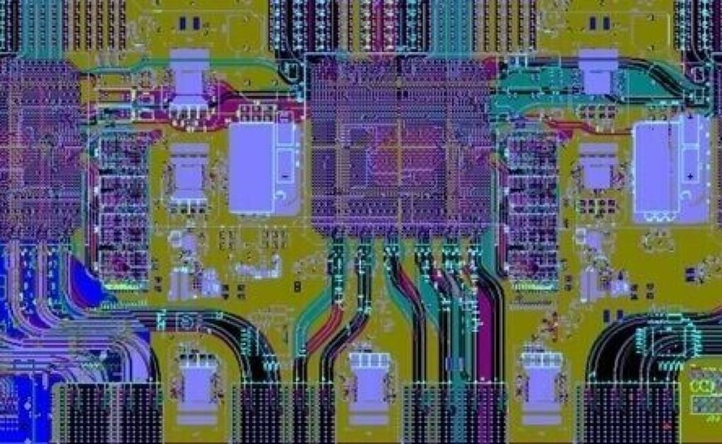
Printed Circuit Boards (PCBs) are an integral part of modern electronics, serving as the foundation for various embedded systems. In the electronic design industry, the final output of most embedded product designs is often in the form of PCB files. These files represent the complete circuit layout and are critical for manufacturing.
Typically, a PCB project consists of four key files:
- xxx.SchDoc: PCB schematic diagram
- xxx.PcbDoc: PCB layout or package diagram
- xxx.SchLib: PCB schematic library
- xxx.PcbLib: PCB package library
Get a free quote now!
The workflow generally follows this process:
- Start by drawing the PCB schematic library (SchLib).
- Then, create the PCB packaging library (PcbLib), linking the schematic components to their package equivalents.
- Draw the PCB schematic diagram (SchDoc) and update it to the PCB layout (PcbDoc).
- Use the Design menu to update the PCB document and finally move on to copper layout.
Introduction to Gerber Files
Gerber files, also known as photo files, are the standard format for PCB manufacturing. These files consist of two main parts:
- Gerber Photo File: Describes the details of a single PCB layer.
- NC Drill File: Specifies drilling locations for components.
PCB manufacturers use Gerber files to fabricate the final PCB, with the widely used format being RS-274X. More recent formats like Gerber X2 provide additional information, such as layer stack-up details and board attributes.
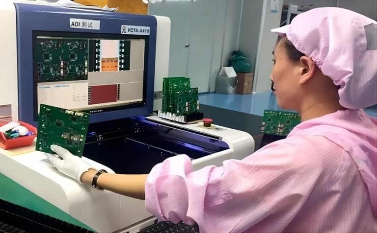
While some designers may prefer sending raw PCB files to manufacturers, this practice carries risks. Since manufacturers must convert PCB files into Gerber format, discrepancies can arise. Therefore, experienced engineers manually convert their PCB files to Gerber format, using software tools like CAM350 to verify accuracy before sending them for production.
Key Components of Gerber Files
A typical Gerber file includes the following:
- Outline
- CNC Drill (Plated & Non-Plated)
- Silkscreen Layer
- Solder Mask Layer
- Copper Layer
- Solder Paste Layer
These elements ensure the PCB design is accurately interpreted and manufactured.
How to identify correct Gerber files
Gerber files consist of two essential components:
- D-code: Defines the trace width and pad dimensions.
- Coordinates: Specify the exact placement of elements on the board.
PCB manufacturers use Gerber files to fabricate the final PCB, with the widely used format being RS-274X. More recent formats like Gerber X2 provide additional information, such as layer stack-up details and board attributes.

While some designers may prefer sending raw PCB files to manufacturers, this practice carries risks. Since manufacturers must convert PCB files into Gerber format, discrepancies can arise. Therefore, experienced engineers manually convert their PCB files to Gerber format, using software tools like CAM350 to verify accuracy before sending them for production.
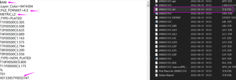
CNC files, including DDR files and drill files, contain important details such as hole size, count, and whether the holes are plated or not. Drill files typically follow a “TXT” format and provide the necessary coordinates for drilling operations in PCB production.

Common PCB File Suffixes
Different Electronic Design Automation (EDA) tools use various file formats for PCB design:
- Protel/Altium Designer: .pcb or .pcbdoc
- Cadstar/CR5000 (ZUKEN): .pcb
- Allegro/Eagle (Cadence): .brd
- PADS/Protel/P-cad (text format): .asc
- CAM350: .cam
- ODB++: .tgz
How to Open PCB Files
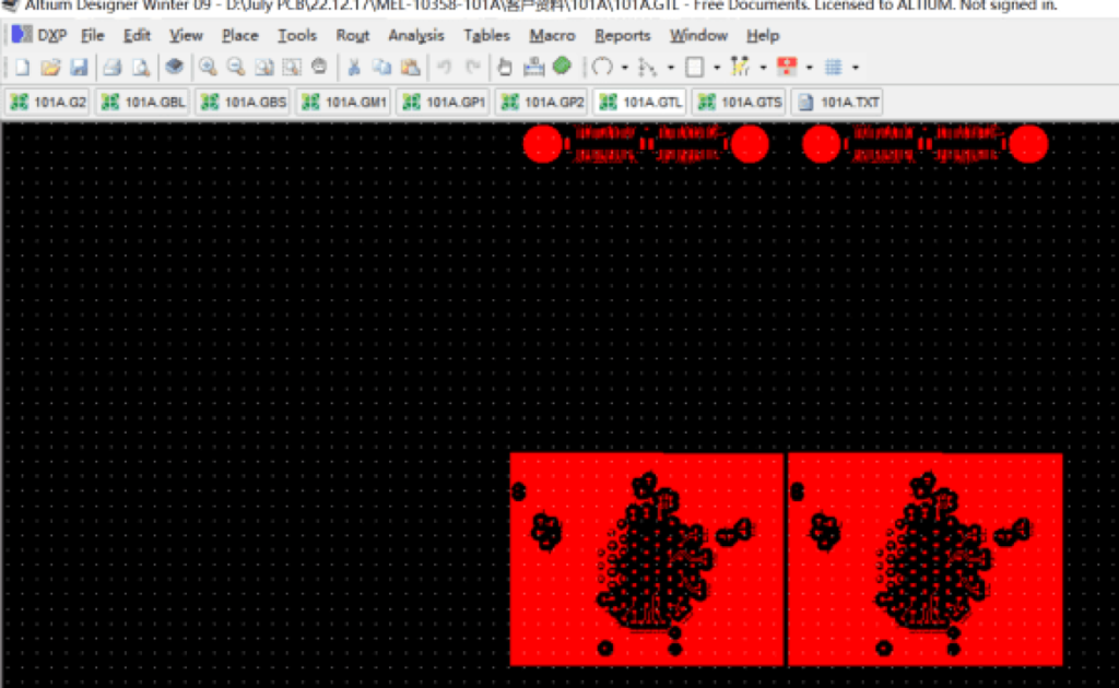
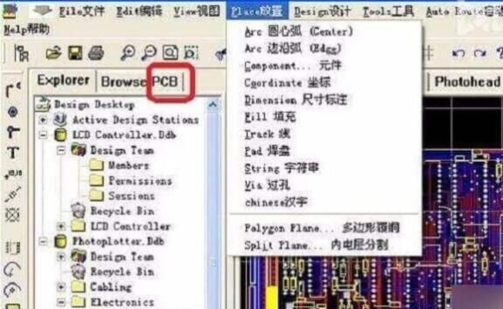
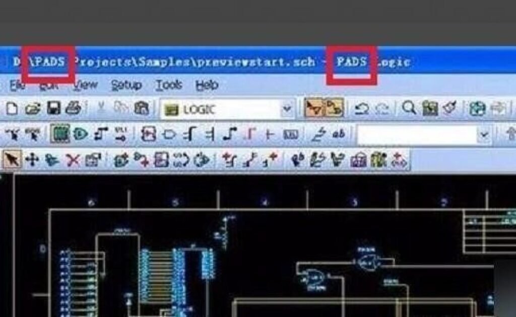
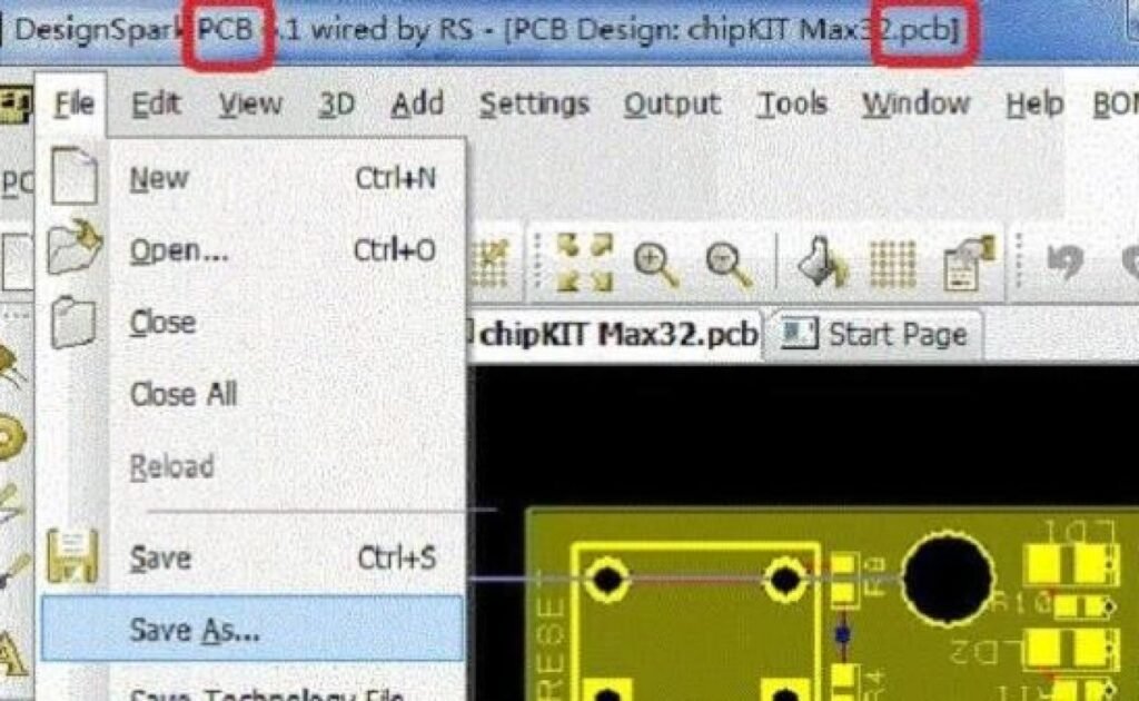
PCB files can be opened with Protel software.
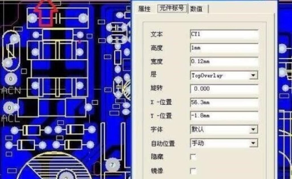
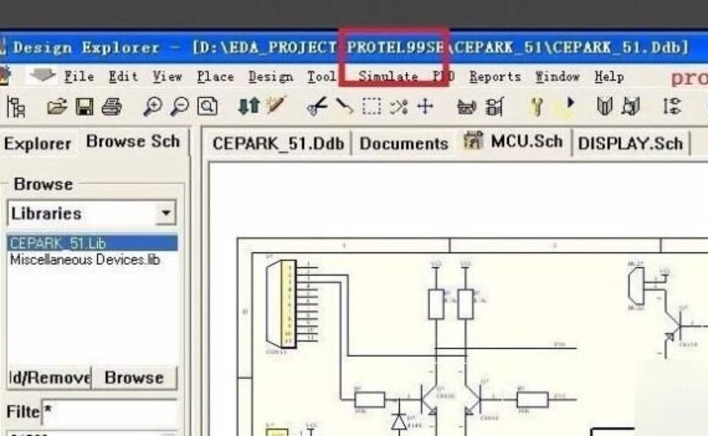
This software is the modern version of Protel, fully supporting PCB files.
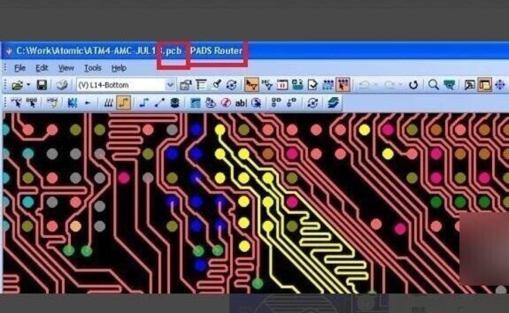
We can also select the PADS software that is also easy to use as below. Pads software for high-end circuit design.
Converting Gerber Files to PCB Files
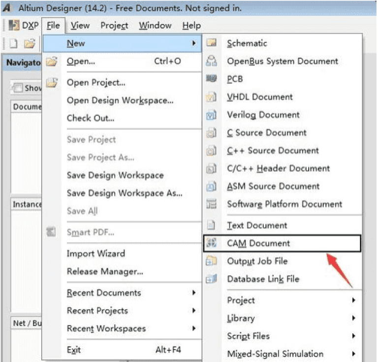
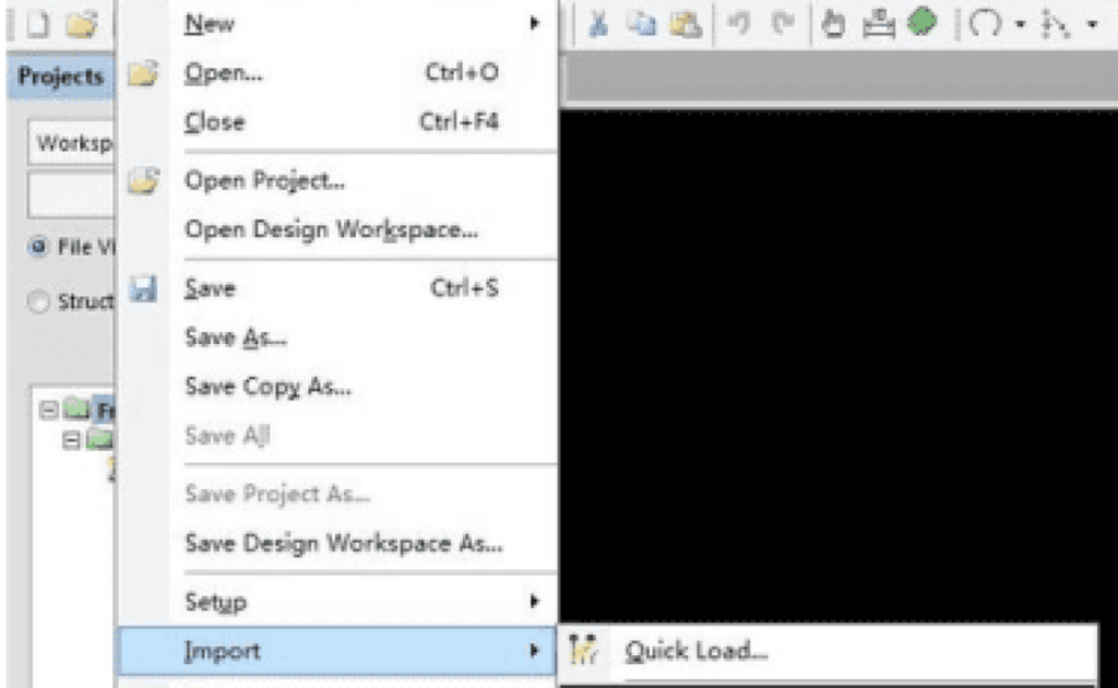
To convert Gerber files into PCB files, there are two common methods:
Export Gerber to DXF format and import it into a blank PCB project.
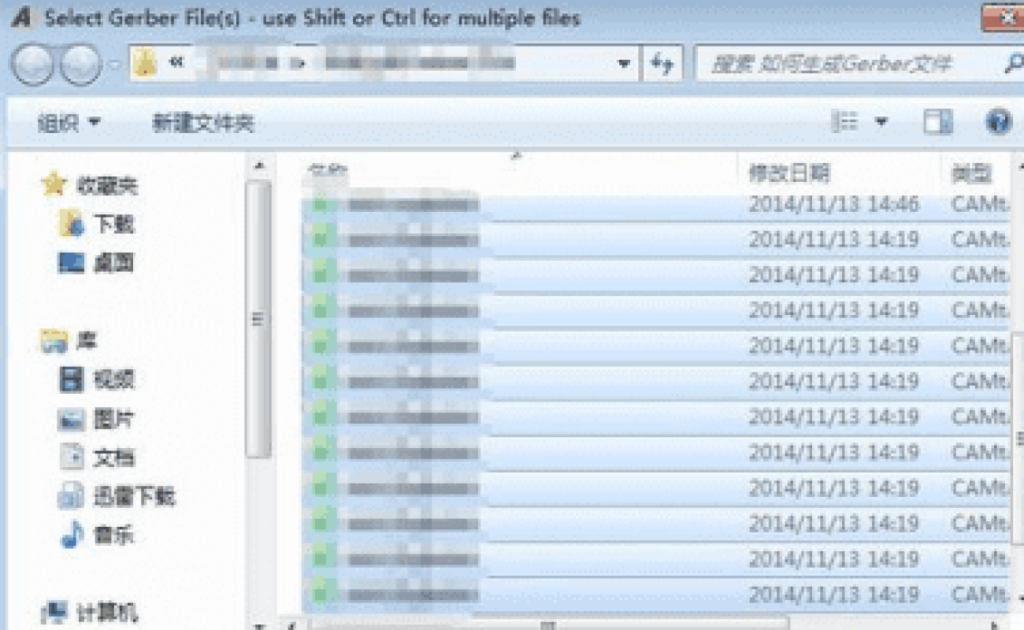
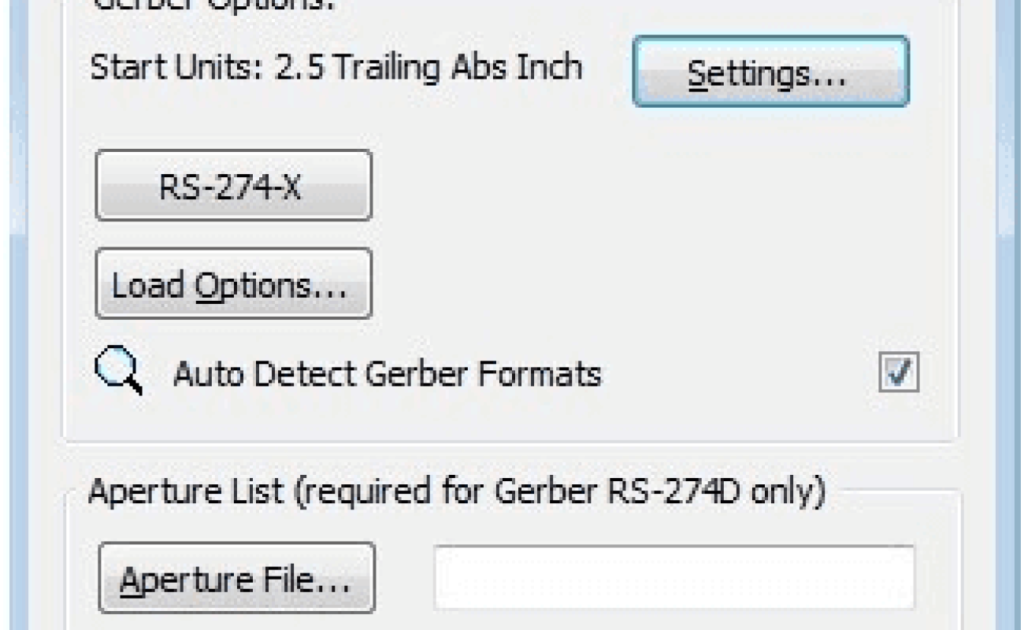
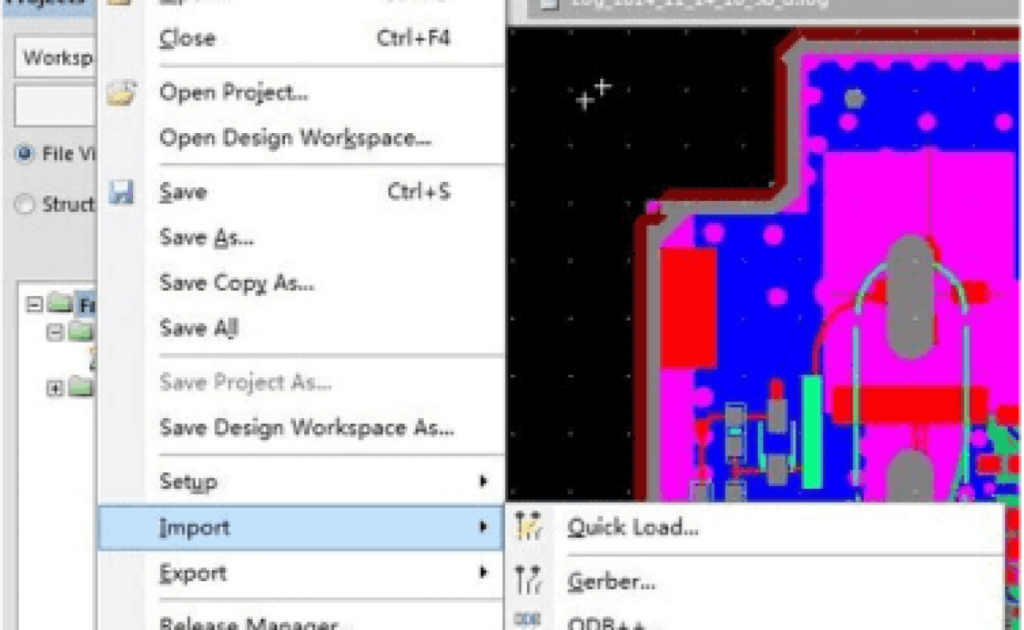
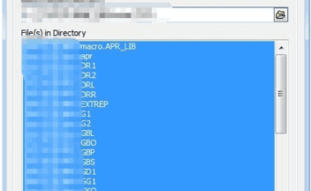
Import Gerber files layer by layer, including the NC Drill file, and optionally, the IPC-D-356 netlist for network naming accuracy.
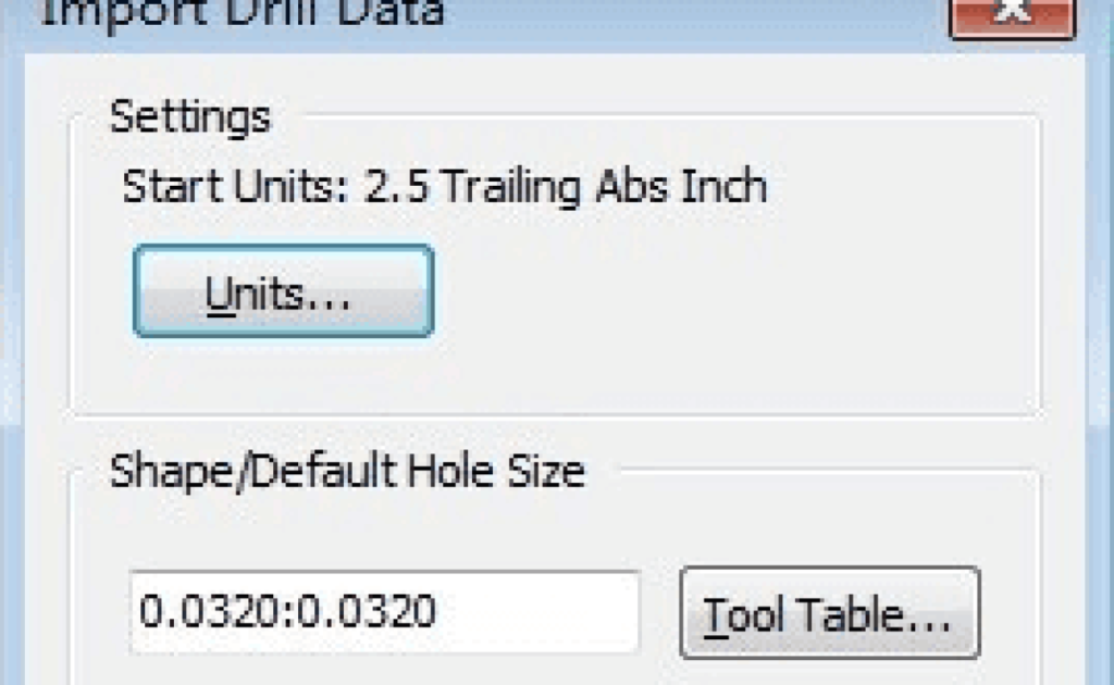
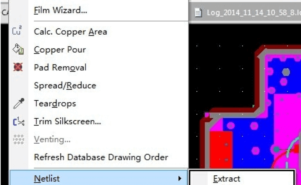
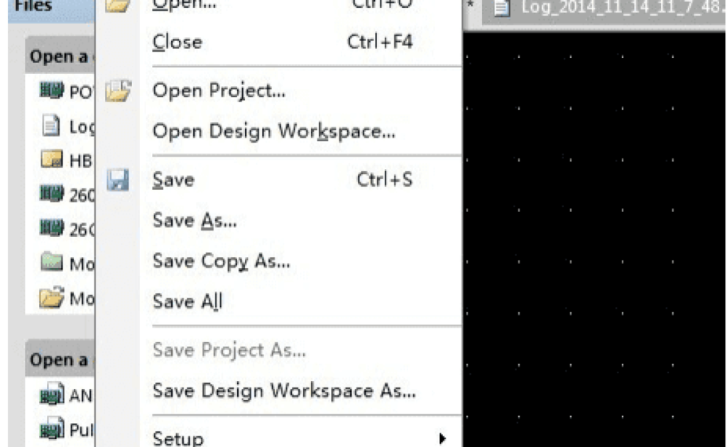
PCB File Transfer to GERBER
Transferring a PCB file to GERBER format involves two essential steps:
- Generation of GERBER files
- Generation of NC drilling files
Open Altium Designer and select Menu > File > Open to access the required PcbDoc file. Once the file is open, go to Menu > File > Export and choose the Gerber file option.
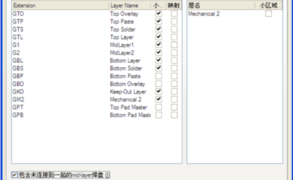
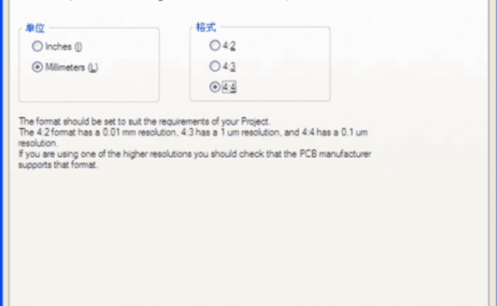
When generating CNC files, ensure that you set the appropriate units—either English (inch) or metric (millimeters). You should also configure the precision, typically in the format of 4:4 or 4:3. For most cases, the metric system is used with a 4:4 precision.
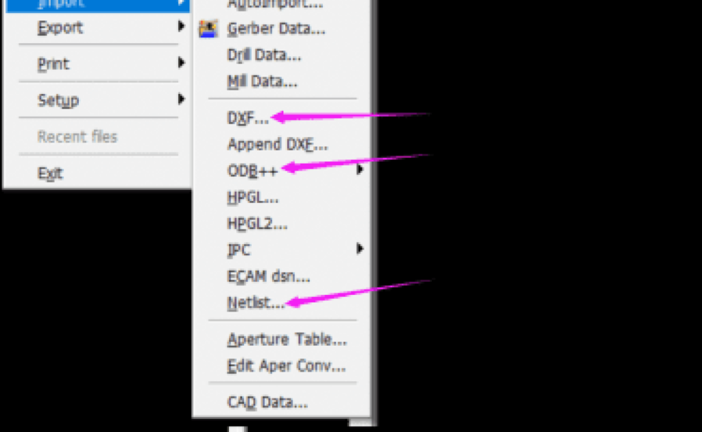
Using software like CAM350, converting a DXF file to GERBER is straightforward:
- Go to File > Import, then select the DXF file.
- If the source file is in ODB++ format from Genesis2000 software, it can also be recognized.
To export CAM files to a PCB format:
- Navigate to File > Export and choose Export to PCB.
- Ensure that the network table has been generated in the previous steps, as this is necessary for successful PCB export.
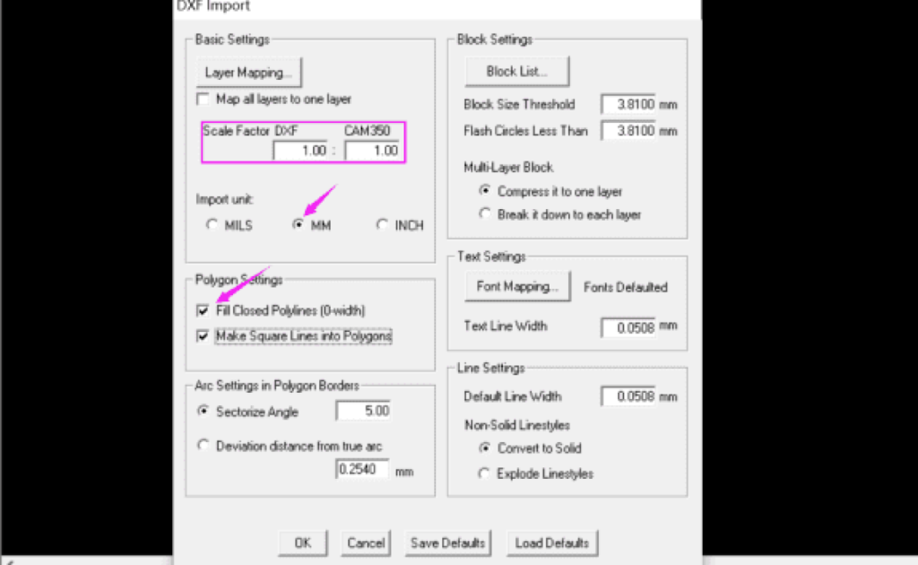
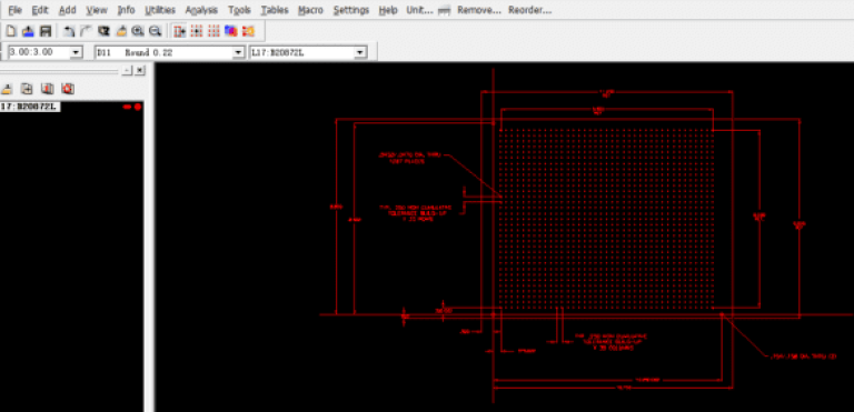
When transferring DXF files to GERBER format, it’s essential to compare or confirm the recognition of special-shaped pads with the original file to avoid any hidden issues. Remember, different software platforms have their own limitations, and not all software is universally compatible.
Connect with us
Get an Instant Online Quote Today
Looking for reliable SMD assembly services? At ESPCBA, we’re your trusted partner for PCB fabrication, component sourcing, and electronic manufacturing. With over 16 years of experience, we’ve provided high-quality PCBs at competitive prices to over 1,000 customers worldwide. Our company is ISO9001:2015 certified and UL listed, and every product we deliver is 100% E-tested and inspected using AOI and X-ray to meet the highest standards. Get an instant quote from our sales team today, and let us handle the rest for you.