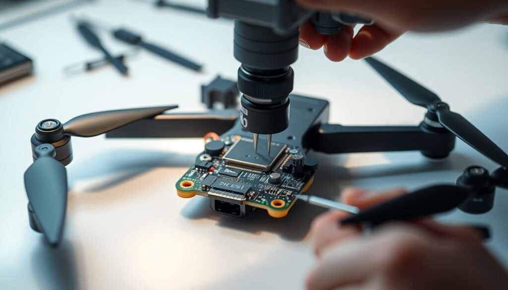
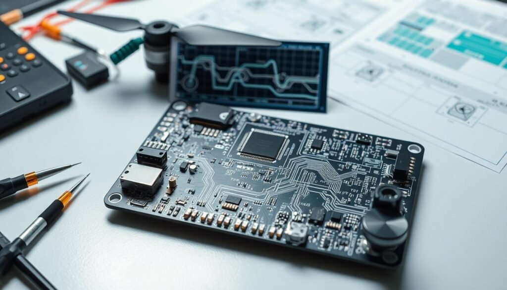
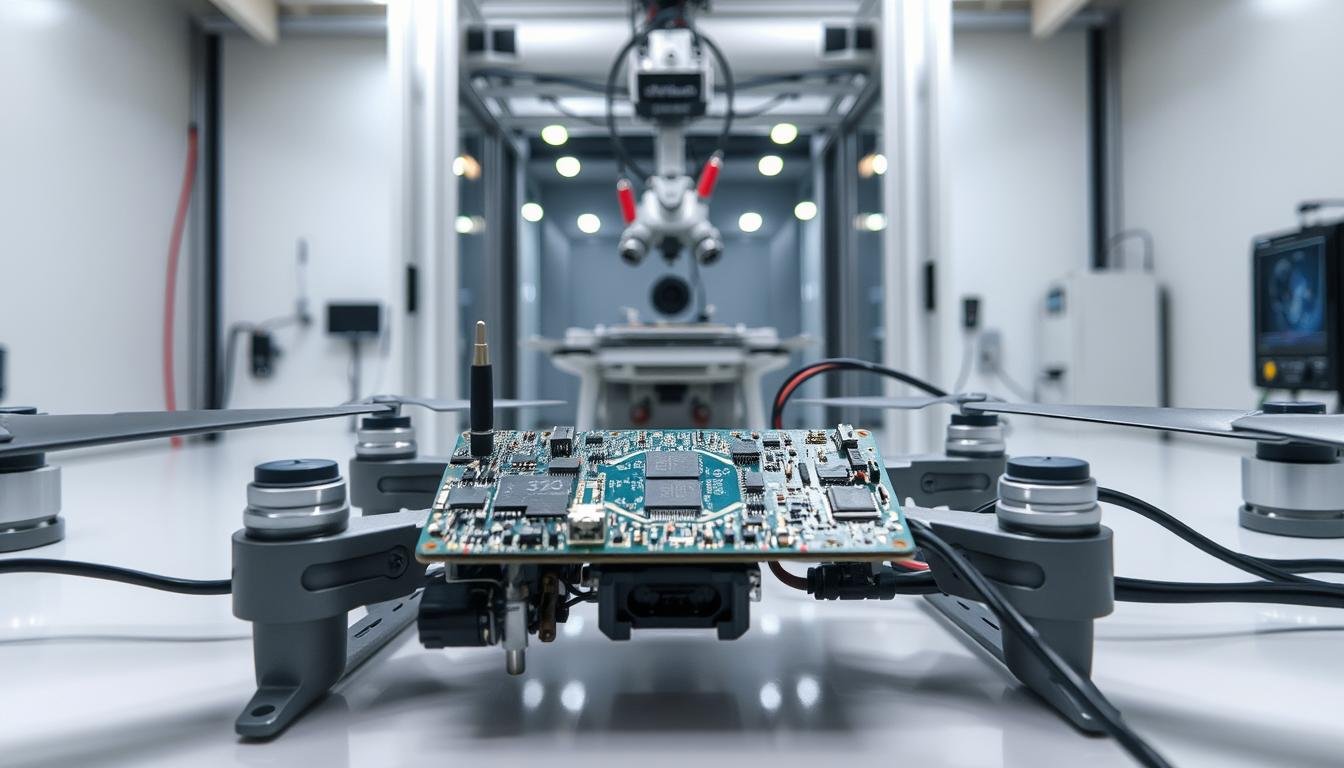
Modern drone performance hinges on circuit boards that withstand extreme conditions. We combine decades of aerospace experience with advanced diagnostic tools to validate every component in mission-critical systems. Our methodology focuses on three core principles: precision, durability, and repeatability.
Signal integrity remains paramount for stable communication between flight controllers and propulsion systems. Our team evaluates power distribution networks under simulated flight loads, ensuring consistent performance during rapid maneuvers. Environmental testing chambers replicate temperature shifts and vibration patterns encountered during operation.
Automated optical inspection complements manual quality checks, creating multiple verification layers. This dual approach catches microscopic flaws that could compromise long-term functionality. For high-stakes applications, we conduct accelerated life testing to predict component behavior over years of use.
Key Takeaways
- Rigorous evaluation protocols exceed standard industry requirements
- Combined manual and automated inspection ensures defect detection
- Environmental simulations test real-world operating conditions
- Power distribution analysis prevents voltage drops during flight
- Systematic documentation provides traceable quality records
Introduction to Drone PCBA Testing
Precision-crafted circuit boards form the operational core of modern aerial devices. These specialized drone PCB designs manage everything from motor control to sensor integration, acting as the central hub for electronic communication. Unlike standard boards, they handle higher current loads while maintaining compact dimensions – a critical balance for airborne systems.
Understanding the Role of PCBAs in Drones
Every unmanned aircraft relies on its circuit board to coordinate power flow and data transmission. These boards distribute clean voltage to motors and cameras while processing real-time flight data. Their layered architecture supports simultaneous functions: stabilizing rotors, managing battery output, and relaying GPS coordinates.
Why Reliability Is Paramount Before Flight
A single flaw in PCB components can disrupt navigation or cause mid-air failures. Boards must endure rapid temperature shifts and constant vibrations without performance drops. Rigorous validation protocols verify each connection point and trace path before installation, preventing costly operational risks.
Advanced materials like polyimide substrates help achieve the required durability-to-weight ratio. This ensures consistent power delivery during aggressive maneuvers while resisting environmental stressors unique to aerial operations.
Our Testing Process for Ensuring Drone PCBA Reliability Before Flight
Electronics validation determines operational success in aerial systems. Our framework evaluates circuit boards through four progressive phases: design verification, functional analysis, environmental simulation, and full-system integration. Each stage builds upon previous results to confirm component behavior matches theoretical models.
Automated inspection tools scan pcb layouts for microscopic cracks or soldering defects. Manual checks then validate thermal management and signal paths under load. This dual-method approach identifies issues that single-phase evaluations might miss, particularly in high-frequency communication circuits.
Real-world simulations expose boards to temperature extremes (-40°C to 85°C) and vibration frequencies matching actual flight profiles. We replicate sudden wind gusts and altitude changes to test power stability during aggressive maneuvers. Accelerated aging protocols predict long-term performance by compressing years of use into controlled lab trials.
Key aspects of our validation system:
- Component-level stress tests before assembly integration
- Continuous data logging during thermal cycling
- Post-test failure analysis with root-cause documentation
Field data from deployed systems feeds back into our quality enhancement cycle. This closed-loop process ensures every drone pcb iteration improves upon previous versions, maintaining alignment with evolving aviation standards.
Pre-Flight Inspection and Test Planning

Successful aerial operations demand meticulous preparation at every design step. We establish baseline performance metrics through structured evaluation protocols, creating actionable benchmarks for circuit board validation.
Key Pre-Test Checkpoints
Visual analysis forms the foundation of quality assurance. Technicians examine trace geometry and component alignment against pcb design schematics. Connector stability and solder joint integrity receive special attention to prevent mid-air disconnections.
Power distribution networks undergo preliminary load testing. This verifies voltage consistency across motor controllers and sensor arrays. Thermal imaging identifies potential hotspots before environmental simulations begin.
Design and Functional Requirements
Circuit layouts must balance spatial constraints with signal clarity. Our team cross-references functional requirements with physical dimensions to optimize component placement. Multi-layer boards undergo impedance testing to ensure clean data transmission.
| Checkpoint | Validation Method | Acceptance Criteria |
|---|---|---|
| Trace Width | Microscopic Measurement | ±5% of spec |
| Voltage Stability | Dynamic Load Testing | |
| Signal Noise | Spectrum Analysis | |
| Thermal Spread | Infrared Imaging |
Material selection directly impacts long-term functionality. Rigid-flex substrates undergo bend testing to confirm durability under repeated stress. Final documentation captures every design step, creating traceable records for future iterations.
PCB Design and Circuit Integrity Evaluation

Circuit board architecture directly impacts aerial system responsiveness and error rates. Optimal signal integrity requires strategic component placement and advanced routing techniques to prevent data corruption during high-speed operations.
Signal Integrity Analysis
High-frequency circuits demand precise impedance matching to maintain clean data transmission. Advanced simulation tools model electromagnetic interactions between traces, identifying potential interference hotspots before physical prototyping. Real-time monitoring during load variations confirms stable performance across temperature fluctuations.
We employ time-domain reflectometry to verify signal path quality, ensuring reflections stay within 5% of transmitted power. Cross-talk analysis between parallel traces prevents data packet collisions in multi-layer PCB designs, particularly near motor controllers and RF modules.
Trace and Layout Considerations
High-density interconnect technology enables compact routing through micro-vias and stacked layer transitions. This approach reduces signal path lengths by 40-60% compared to conventional layouts, critical for real-time video streaming applications.
Key layout principles for drone circuits:
- Differential pair routing for high-speed communication lines
- Controlled impedance traces matched to component specifications
- Strategic ground plane placement to minimize EMI radiation
Thermal relief patterns prevent solder joint stress during rapid temperature changes, while copper balancing ensures even heat distribution. These design strategies collectively enhance circuit longevity without compromising signal fidelity.
Drone PCB Material Quality and Durability Checks
Circuit board longevity depends on selecting substrates that match operational demands. Material scientists evaluate thermal expansion rates and chemical resistance to identify optimal solutions for aerial electronics. Advanced polymers provide critical advantages over traditional FR-4 laminates in dynamic environments.
Analyzing Polyimide, PET, and Other Materials
Polyimide dominates drone pcb construction with unmatched temperature tolerance. These substrates maintain structural integrity from -269°C to 400°C, surviving arctic surveys and desert reconnaissance missions. Their molecular flexibility allows tight folding around gimbal assemblies without cracking conductive traces.
Chemical resistance testing proves essential for boards exposed to aviation fuels and de-icing fluids. Polyimide samples undergo immersion in aggressive solvents while monitoring electrical continuity. This ensures stable performance when drones operate near industrial sites or coastal regions.
| Material | Max Temp | Flex Cycles | Chemical Resistance |
|---|---|---|---|
| Polyimide | 400°C | 500k+ | Excellent |
| PET | 150°C | 100k | Good |
| FR-4 | 130°C | 50k | Fair |
Polyester (PET) serves budget-conscious projects requiring moderate durability. While less heat-resistant than polyimide, it withstands typical consumer drone conditions. Accelerated aging tests simulate five years of flight vibrations to verify connection stability across materials.
Quality teams implement strict incoming inspection protocols for all pcb boards. Each polymer batch undergoes bend testing and thermal cycling before approval. This multi-stage verification prevents material defects from compromising final products.
Evaluating Power Management and Performance Efficiency
Power systems act as the circulatory network of aerial devices, determining operational endurance and responsiveness. Advanced power distribution boards (PDBs) coordinate energy flow between lithium polymer batteries and propulsion systems while managing sensor arrays. These critical components require precision engineering to balance current demands across motors, cameras, and navigation modules.
Assessing Battery Impact and Power Distribution
Voltage regulation proves essential for maintaining stable operations during aggressive maneuvers. We implement real-time monitoring of energy consumption patterns across flight modes, identifying optimization opportunities. Thermal imaging reveals heat dissipation efficiency in high-current pathways – a key factor in preventing component degradation.
Three core evaluation metrics guide our analysis:
- Voltage consistency under sudden load changes (0-100% throttle)
- Energy loss percentages during data transmission bursts
- Recovery time after brownout scenarios
Modern PDB designs integrate advanced circuit analysis techniques to minimize electromagnetic interference between power traces and signal lines. This prevents voltage drops in motor controllers while ensuring clean energy supply to gyroscopes and GPS receivers. Field tests confirm designs achieve 92-97% power efficiency across temperature extremes.
Battery lifespan directly correlates with proper current distribution. Our protocols simulate multi-rotor stress conditions to validate that 40A+ surges don’t compromise sensor accuracy. This dual focus on raw power delivery and micro-level energy management extends flight times while maintaining operational safety margins.
Environmental Stress Testing and Vibration Resistance
Aerial electronics face relentless environmental challenges requiring rigorous validation. We expose circuit boards to conditions mimicking harsh operational realities, from desert heatwaves to arctic blizzards. This proactive approach identifies failure points before deployment.
Temperature Cycling and Extreme Condition Testing
Thermal shock protocols cycle boards between -40°C and 125°C, replicating altitude changes and seasonal extremes. Polyimide substrates demonstrate exceptional stability, maintaining conductivity through 500+ cycles. Humidity chambers simulate tropical conditions, testing conformal coating effectiveness against moisture ingress.
Salt fog testing proves critical for coastal operations, with specialized boards designed for military applications surviving 96-hour exposure without corrosion. These evaluations ensure components withstand decade-equivalent wear in compressed timelines.
Simulating Vibration and Mechanical Shock
Custom jigs replicate rotor-induced harmonics and landing impacts. Accelerometers measure resonant frequencies that could fracture solder joints. Flexible materials absorb 90% of vibrational energy, protecting micro-BGA packages during aggressive maneuvers.
Drop tests validate crash resilience, with advanced laminates surviving 6-foot impacts onto concrete. Fatigue analysis predicts connection durability across 10,000+ flight hours. This multi-stage validation process creates boards that outlast airframe components.
FAQ
How do PCB design choices impact drone flight performance?
What material considerations matter most for drone circuit boards?
How do you validate power management systems in drone PCBs?
What environmental tests guarantee PCB durability in drones?
How does component placement affect drone functionality?
What quality checks ensure reliable solder joints?
About The Author
Elena Tang
Hi, I’m Elena Tang, founder of ESPCBA. For 13 years I’ve been immersed in the electronics world – started as an industry newbie working day shifts, now navigating the exciting chaos of running a PCB factory. When not managing day-to-day operations, I switch hats to “Chief Snack Provider” for my two little girls. Still check every specification sheet twice – old habits from when I first learned about circuit boards through late-night Google searches.
