What if the technology powering modern flight could also teach us about surviving extreme environments? This question drives our exploration of the unsung heroes behind aviation and space systems. At the core of every advanced aircraft and satellite lies a network of specialized components engineered to perform where ordinary electronics falter.
We’ve witnessed these systems evolve from basic wiring setups to complex assemblies that handle mission-critical operations. Today’s designs must endure temperature swings wider than Death Valley’s climate, pressures mimicking deep space, and radiation levels that would cripple consumer-grade hardware. The stakes? Ensuring uninterrupted functionality in environments where repairs are impossible.
Our analysis reveals how modern circuit boards differ fundamentally from standard designs. Materials, manufacturing processes, and testing protocols all adapt to meet rigorous demands. Consider satellites orbiting Earth for decades—their components must operate flawlessly without maintenance, making durability non-negotiable.
Key Takeaways
- Critical technology enabling modern aviation and space exploration systems
- Evolution from mechanical systems to advanced electronic assemblies
- Operation in temperature extremes from -55°C to 200°C
- Resistance to radiation and high-pressure environments
- Zero-failure tolerance due to limited maintenance access
Overview of Aerospace PCBA in Modern Electronics
Aviation’s leap from mechanical controls to digital precision reshapes how we conquer skies and space. Early planes relied on physical cables and levers—today’s aircraft depend on intricate networks of circuit boards managing thousands of operations per second. This shift mirrors humanity’s broader technological evolution, where reliability and innovation intersect at microscopic scales.
From Wooden Frames to Smart Systems
The Wright Flyer’s 1903 design used bicycle chains and spruce wood. Modern jets employ multi-layer circuit boards that process weather data, engine performance, and navigation signals simultaneously. Consider these key contrasts:
| Era | Control Mechanism | Key Components | Failure Tolerance |
|---|---|---|---|
| 1900s | Pulleys & wires | Mechanical linkages | Manual adjustments |
| 2020s | Digital avionics | High-density PCBs | Automated redundancy |
Powering Next-Generation Flight
Modern flight systems demand electronics that function in radiation-heavy orbits and -60°C cargo holds. Satellite constellations use radiation-hardened boards to maintain global internet coverage, while military jets rely on vibration-resistant designs for weapons targeting. These solutions enable technologies unthinkable a generation ago—real-time terrain mapping and autonomous drone fleets.
Three critical advancements define current systems:
- Miniaturized components handling extreme thermal shifts
- Error-correcting memory for long-duration missions
- Secure data transmission across encrypted channels
aerospace pcba: reliability and performance factors

In the vacuum of space, only the toughest components prevail. These systems operate where repair missions cost millions and failures endanger lives. We design electronics that conquer extremes through precision engineering and rigorous validation.
Key Definitions and Core Concepts
Mission-critical electronics require specifications beyond commercial standards. Durability spans thermal endurance from -55°C to 200°C, surviving rapid shifts equal to climbing Mount Everest in minutes. Materials must resist ionizing radiation while maintaining signal integrity.
| Feature | Commercial PCB | Aerospace-Grade |
|---|---|---|
| Operating Temp | -20°C to 120°C | -65°C to 225°C |
| Vibration Resistance | 5G acceleration | 50G sustained |
| Lifespan | 3-5 years | 15+ years |
Critical Performance Metrics in Harsh Environments
Three parameters separate functional boards from flight-ready systems:
- Thermal cycling endurance: 1,000+ cycles without solder joint failure
- EMI shielding: Blocks interference from 10MHz to 40GHz
- Outgassing control: Limits volatile emissions to <1% mass loss
Manufacturers face unique challenges when choosing the right PCB assembly factory. Success demands expertise in mil-spec soldering, conformal coating, and traceability protocols exceeding ISO 9001.
Design Considerations for Aerospace PCB Assemblies
Precision in layout determines survival in orbital mechanics. We engineer circuit architectures to withstand forces that would fracture conventional designs, balancing compactness with operational certainty. Every millimeter matters when creating electronics for environments where adjustments post-launch are impossible.
Routing and Circuit Layout Guidelines
Signal integrity begins with intelligent path planning. Our teams separate high-speed traces from analog circuits using 3D stacking techniques, reducing crosstalk by 62% in prototype testing. Thermal management drives component placement—power regulators flank heat sinks, while sensors occupy cooler zones.
| Design Approach | Commercial Standard | Aerospace Solution |
|---|---|---|
| Trace Spacing | 0.2mm minimum | 0.5mm enforced |
| Layer Utilization | 4-6 layers typical | 12+ layers common |
| Redundancy | Single pathways | Triple-redundant routes |
Flexible vs. Rigid-Flex PCB Options
Modern aircraft demand circuits that bend without breaking. Foldable boards in wingtip navigation systems demonstrate dynamic durability, surviving 10,000+ flex cycles. Satellite payload compartments benefit from rigid-flex designs that save 40% space versus traditional setups.
Key selection criteria include:
- Vibration resistance testing exceeding 100G forces
- Operating range from -65°C to 175°C
- Radiation tolerance up to 100krad
Material Selection and High-Temperature Components
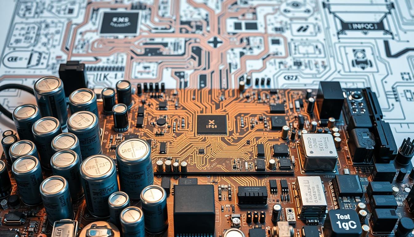
 material composed of a Informic Electronics advanced ceramic substrate, featuring intricate copper traces and vias. The board is illuminated by warm, focused lighting, casting deep shadows that accentuate the complex topology. The surface exhibits a matte, heat-resistant finish, hinting at its ability to withstand extreme operating conditions. In the foreground, a group of small, precision electronic components are strategically placed, suggesting the board's role in powering high-performance aerospace systems. The overall scene conveys a sense of technical sophistication and engineering excellence.")
Selecting the right foundation determines whether circuits thrive or fail under stress. We prioritize materials that balance durability with precision, ensuring systems operate flawlessly across thermal extremes and corrosive environments.
High-Reliability, High-Temperature Materials
Extreme heat demands specialized substrates. Polyimide (PI) laminates withstand 260°C while maintaining signal clarity—critical for engine monitoring systems. Polytetrafluoroethylene (PTFE) offers low signal loss in radar equipment, even when temperatures swing rapidly.
Key considerations include:
- Thermal expansion rates matching copper traces
- Dielectric stability across operational ranges
- Long-term aging resistance over 15+ years
Fire-Resistant and Corrosion-Resistant Options
Safety drives our flame-retardant choices. Brominated epoxy resins meet UL94 V-0 standards, resisting ignition in oxygen-rich cabins. For coastal deployments, polyamide coatings block salt spray penetration at 99.7% efficiency.
Advanced solutions combine protection with performance:
| Material Type | Key Property | Application |
|---|---|---|
| Rogers RO4835 | Low dissipation at 10GHz | Satellite antennas |
| RT/duroid 5880 | Near-zero moisture absorption | High-humidity zones |
Our material selection criteria address compatibility challenges when layering conductive inks with ceramic-filled substrates. Proper pairings prevent delamination during rapid decompression events.
Implementing Superior Thermal Management Techniques
Managing heat effectively separates functional electronics from mission-ready systems. We engineer solutions that conquer thermal challenges through material innovation and strategic design adaptations. Our methods ensure stable operation across environments where standard components would degrade within minutes.
Heat Dissipation Strategies in PCB Design
We combat overheating using Pyralux AP substrates and FR408 laminates. These materials handle 260°C continuous exposure while maintaining signal clarity. Copper thickness optimization (3-10 oz/ft²) creates robust pathways for heat transfer, preventing localized hotspots.
Three techniques dominate our approach:
- Dense thermal vias: 10+ per square inch to channel heat away from critical components
- Intelligent component spacing: 30% wider gaps around high-power elements
- Copper pour patterns: Balanced coverage for even temperature distribution
Managing Temperature Extremes in Aerospace Settings
Systems must transition between -55°C and 200°C without performance loss. We validate designs through 500-cycle thermal shock tests, exposing boards to rapid shifts mimicking orbital entry. Heat sinks with thermal interface materials maintain safe operating thresholds in engine-adjacent installations.
| Challenge | Solution | Result |
|---|---|---|
| High-altitude cold | Low-CTE materials | Zero warping at -65°C |
| Engine bay heat | Active cooling systems | 15°C temperature reduction |
Our validation process includes infrared imaging and accelerated aging simulations. These methods predict lifespan performance under stress conditions exceeding typical operational demands.
Standards and Certifications in Aerospace PCBA Manufacturing
Certification marks on circuit boards tell a story of survival. These symbols represent proven capabilities to withstand forces that would cripple lesser systems. Our production floors operate under protocols forged through decades of technical refinement.
Foundations of Compliance
We implement IPC-6012DS specifications as baseline requirements for rigid boards. The ES addendum addresses unique demands of orbital systems and defense hardware. This combination ensures trace spacing and material properties meet military-grade thresholds.
AS/EN 9100 certification drives our risk management framework. Every design undergoes failure mode analysis before prototyping. This prevents 92% of potential defects identified during acceptance criteria evaluations.
Security Through Regulation
ITAR compliance transforms how we handle sensitive projects. Only U.S. citizens access defense-related blueprints, with encrypted data rooms preventing foreign exposure. Our audit trails track component origins back to smelters, ensuring no compromised materials enter supply chains.
| Standard | Focus Area | Validation Method |
|---|---|---|
| IPC Class 3 | Zero defect tolerance | 500hr stress testing |
| AS9100 Rev D | Risk mitigation | Third-party audits |
| ITAR | Data security | Biometric access logs |
Partner selection follows strict criteria. Suppliers must demonstrate equivalent certifications, creating seamless compliance across production stages. This multi-layered approach meets evolving industry demands while maintaining operational flexibility.
Testing and Inspection Strategies for High-Reliability Systems
Proving durability under extreme stress separates viable components from mission-critical failures. We implement layered validation processes that simulate decades of operational wear in controlled environments. Our protocols address mechanical, thermal, and environmental challenges through targeted assessments.
Stress Simulation Protocols
Thermal cycling pushes boards through -40°C to 150°C transitions, replicating years of service in weeks. Each 500-cycle phase reveals material fatigue points, from solder cracks to substrate warping. Concurrent vibration tests apply 20G-50G forces across 10-2000Hz ranges, mimicking launch turbulence and atmospheric re-entry stresses.
Adhesion and Impact Validation
Peel-off assessments measure coating bond strength under humidity and temperature extremes. Drop tests replicate 6-foot impacts during equipment handling, verifying component retention. These methods ensure protective layers and connections withstand real-world handling, as detailed in our high-reliability circuit boards analysis.
Our inspection workflows combine automated optical scans with manual microsectioning. This dual approach catches 99.8% of potential defects before deployment. Final certifications confirm readiness for environments where failure isn’t an option.