The selection of appropriate PCB laminate materials is a critical decision that directly impacts the performance, reliability, and cost of your printed circuit board design. Whether you’re developing consumer electronics, high-frequency RF applications, or aerospace systems, understanding the properties and applications of different laminate options is essential for successful PCB implementation. This comprehensive guide explores the characteristics of FR-4, Rogers, Polyimide, and other specialty laminates to help you make informed material selection decisions for your specific requirements.
PCB Laminate Materials Selection Guide
Download our comprehensive comparison chart featuring 15+ laminate materials with detailed specifications on thermal properties, dielectric constants, and recommended applications.
The Critical Role of PCB Laminate Materials in Circuit Performance
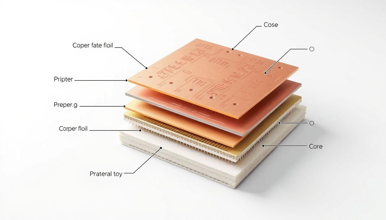
PCB laminate materials serve as the foundation of every printed circuit board, providing structural support while influencing electrical performance. The laminate consists of a dielectric substrate material (typically reinforced with glass or other fibers) and copper foil layers that form the conductive pathways. The properties of these materials directly affect three key aspects of PCB performance:
Cross-section of typical PCB laminate structure showing copper, prepreg, and core layers
Thermal Stability
The glass transition temperature (Tg) and decomposition temperature (Td) determine how a laminate behaves when exposed to heat during manufacturing and operation. Higher Tg materials maintain their mechanical and electrical properties at elevated temperatures, making them suitable for lead-free soldering processes and high-temperature applications.
Dielectric Properties
The dielectric constant (Dk) and dissipation factor (Df) influence signal propagation and loss. Materials with lower Dk values allow faster signal transmission, while lower Df values reduce signal loss—critical factors in high-frequency and high-speed digital applications where signal integrity is paramount.
Mechanical Strength
The physical properties of laminates, including flexural strength, coefficient of thermal expansion (CTE), and moisture absorption, affect the board’s durability and reliability. These factors determine how the PCB withstands mechanical stress, temperature cycling, and environmental conditions throughout its operational life.
FR-4: The Industry Standard PCB Laminate Material
FR-4 (Flame Retardant 4) is the most widely used PCB laminate material, serving as the baseline for comparison with other options. It consists of woven fiberglass cloth impregnated with an epoxy resin binder, offering a balanced combination of performance, manufacturability, and cost.

FR-4 laminate showing characteristic woven fiberglass structure
Key Properties of FR-4 Laminates
- Glass Transition Temperature (Tg): Standard FR-4 has a Tg of 130-140°C, while high-Tg variants offer 170-180°C
- Dielectric Constant (Dk): Typically 4.0-4.5 at 1 MHz, with some variation based on resin content
- Dissipation Factor (Df): Approximately 0.02 at 1 MHz
- Thermal Conductivity: 0.3-0.4 W/mK
- Coefficient of Thermal Expansion (CTE): X/Y: 14-17 ppm/°C, Z: 50-70 ppm/°C
- Moisture Absorption: 0.10-0.15%
- Flexural Strength: 550-650 MPa
- Peel Strength: 1.05-1.4 N/mm
- Decomposition Temperature (Td): 310-350°C
- Cost Range: Low to moderate ($1-3 per square foot, depending on grade and thickness)
Applications of FR-4 Laminates
FR-4 is the go-to material for a wide range of applications due to its versatility and cost-effectiveness:
- Consumer electronics (smartphones, computers, televisions)
- Industrial control systems
- Automotive electronics (non-critical systems)
- Telecommunications equipment
- General-purpose electronic devices operating below 1-2 GHz
Manufacturing Consideration: High-Tg FR-4 variants (170-180°C) were developed to withstand lead-free soldering processes, which require higher temperatures than traditional tin-lead soldering. These materials offer improved thermal reliability while maintaining the familiar processing characteristics of standard FR-4.
Rogers Laminates: High-Performance Materials for RF and Microwave Applications
Rogers Corporation produces a range of high-performance laminate materials specifically designed for radio frequency (RF) and microwave applications. These materials offer superior electrical properties compared to FR-4, making them ideal for high-frequency circuits where signal integrity is critical.

Rogers laminate material in a high-frequency RF application
Key Rogers Laminate Series
RO4000® Series
The RO4000 series (including RO4350B and RO4003C) bridges the gap between FR-4 and PTFE-based materials, offering excellent electrical performance with FR-4-like processing. These materials use a hydrocarbon/ceramic matrix with glass reinforcement.
Real-world example: RO4350B is widely used in automotive radar systems operating at 77 GHz for advanced driver assistance systems (ADAS).
RT/duroid® Series
The RT/duroid series features PTFE composites with various fillers (glass microfiber, ceramic, etc.) for extremely low loss at high frequencies. These materials offer excellent dimensional stability and are used in the most demanding RF applications.
Real-world example: RT/duroid 5880 is used in military radar systems and satellite communication equipment operating above 10 GHz.
TMM® Series
The TMM (Thermoset Microwave Materials) series offers ceramic-loaded thermoset polymer composites with excellent dimensional stability and a low coefficient of thermal expansion, making them suitable for temperature-sensitive applications.
Real-world example: TMM10i is used in base station power amplifiers for 5G telecommunications infrastructure.
Key Properties of Rogers Laminates
- Glass Transition Temperature (Tg): Varies by series; RO4000: >280°C, RT/duroid: N/A (no discrete Tg)
- Dielectric Constant (Dk): Precisely controlled; ranges from 2.2 to 10.2 depending on series
- Dissipation Factor (Df): Very low, typically 0.001-0.004 at 10 GHz
- Thermal Conductivity: 0.5-1.1 W/mK (higher than FR-4)
- Coefficient of Thermal Expansion (CTE): X/Y: 10-14 ppm/°C, Z: 30-50 ppm/°C
- Moisture Absorption: Very low, typically
- Cost Range: High ($15-50+ per square foot, depending on series)
- Dk Stability: Excellent across frequency and temperature
PCB Material Selection Worksheet
Not sure which laminate material is right for your application? Download our interactive worksheet to evaluate your requirements against material properties and get personalized recommendations.
Polyimide Laminates: High-Temperature Performance for Demanding Applications
Polyimide laminates are specialized materials designed for applications requiring exceptional thermal stability, chemical resistance, and dimensional stability. These materials can withstand extreme temperatures and harsh environments, making them ideal for aerospace, military, and industrial applications.

Polyimide laminate material with its characteristic amber/brown color
Key Properties of Polyimide Laminates
- Glass Transition Temperature (Tg): >250°C (significantly higher than FR-4)
- Dielectric Constant (Dk): 3.8-4.5 at 1 MHz
- Dissipation Factor (Df): 0.01-0.02 at 1 MHz
- Thermal Conductivity: 0.3-0.5 W/mK
- Coefficient of Thermal Expansion (CTE): X/Y: 12-16 ppm/°C, Z: 50-60 ppm/°C
- Moisture Absorption: 0.2-0.8% (higher than FR-4)
- Decomposition Temperature (Td): >400°C
- Cost Range: High ($10-30 per square foot)
Applications of Polyimide Laminates
Polyimide laminates excel in applications where extreme conditions are encountered:
- Aerospace and defense electronics
- Automotive engine control modules
- Down-hole drilling equipment for oil and gas exploration
- Industrial equipment operating in high-temperature environments
- Flexible and rigid-flex PCBs requiring high reliability
Manufacturing Consideration: Polyimide laminates absorb more moisture than FR-4, requiring careful handling and storage. Proper baking before lamination and drilling is essential to prevent delamination and other manufacturing defects.
Specialty PCB Laminate Materials for Specific Applications
Beyond the common FR-4, Rogers, and Polyimide materials, several specialty laminates address specific performance requirements. These materials often incorporate unique compositions and manufacturing techniques to achieve particular electrical, thermal, or mechanical properties.

Comparison of specialty PCB laminate materials (left to right): PTFE, ceramic-filled, metal-core, and high-speed digital laminates
PTFE-Based Laminates
Polytetrafluoroethylene (PTFE) laminates offer excellent electrical properties for high-frequency applications. These materials feature very low dielectric constants (Dk: 2.1-2.5) and dissipation factors (Df: 0.0005-0.002), making them ideal for microwave and millimeter-wave circuits.
Key applications: Satellite communications, radar systems, and microwave components operating above 10 GHz.
Manufacturing consideration: PTFE materials require specialized processing techniques different from standard FR-4, including plasma treatment for improved adhesion.
Ceramic-Filled Laminates
Ceramic-filled laminates incorporate ceramic particles into the resin system to enhance thermal conductivity and control dielectric properties. These materials offer a good balance between electrical performance and thermal management.
Key applications: Power electronics, LED lighting modules, and high-power RF amplifiers where heat dissipation is critical.
Real-world example: Isola’s IS680 ceramic-filled laminate is used in power converters for electric vehicles, providing enhanced thermal performance.
Metal-Core PCB Laminates
Metal-core PCB (MCPCB) laminates feature a metal base layer (typically aluminum or copper) with a thin dielectric layer and copper circuit layer. These materials offer superior thermal conductivity for heat-generating applications.
Key applications: High-power LED modules, motor controllers, power supplies, and other heat-intensive applications.
Thermal conductivity: 1-10 W/mK, significantly higher than standard FR-4 (0.3-0.4 W/mK).
High-Speed Digital Laminates
As digital signal speeds continue to increase, specialized laminates have been developed to address the unique challenges of high-speed digital circuits. These materials offer controlled impedance, low signal loss, and minimal skew for applications like servers, networking equipment, and high-performance computing.
Key Properties
- Low and stable dielectric constant (Dk: 3.0-3.8)
- Low dissipation factor (Df: 0.005-0.010)
- Tight glass weave for reduced signal skew
- Improved copper foil adhesion for signal integrity
- Enhanced CAF (Conductive Anodic Filament) resistance
Examples
- Isola Tachyon®: Designed for 100G/400G Ethernet applications
- Panasonic Megtron®: Used in high-speed backplanes and server boards
- Nelco N4000-13: Employed in telecommunications infrastructure
- Shengyi S1000-2: Cost-effective option for consumer high-speed devices
Comprehensive Comparison of PCB Laminate Materials
The following table provides a side-by-side comparison of key properties across different PCB laminate materials to help you evaluate options for your specific application requirements.
| Property | Standard FR-4 | High-Tg FR-4 | Rogers RO4350B | Rogers RT/duroid 5880 | Polyimide | Metal-Core (Al) |
| Glass Transition Temp. (Tg) | 130-140°C | 170-180°C | 280°C+ | N/A | 250°C+ | N/A |
| Dielectric Constant (Dk) | 4.2-4.5 | 4.0-4.3 | 3.48 ±0.05 | 2.20 ±0.02 | 3.8-4.5 | 4.0-7.0 |
| Dissipation Factor (Df) | 0.020 | 0.015 | 0.0037 | 0.0009 | 0.010-0.020 | 0.020-0.030 |
| Thermal Conductivity (W/mK) | 0.3-0.4 | 0.3-0.4 | 0.69 | 0.20 | 0.3-0.5 | 1.0-10.0 |
| CTE Z-axis (ppm/°C) | 50-70 | 40-60 | 32 | 237 | 50-60 | 20-30 |
| Moisture Absorption (%) | 0.10-0.15 | 0.08-0.12 | 0.06 | 0.02 | 0.2-0.8 | 0.05-0.10 |
| Relative Cost | $ | $$ | $$$ | $$$$ | $$$ | $$ |
| Typical Applications | Consumer electronics, general-purpose | Lead-free assembly, multilayer PCBs | Base stations, automotive radar | Satellite communications, millimeter-wave | Aerospace, high-temperature | LED lighting, power electronics |

Signal loss comparison between different PCB laminate materials across frequency ranges (1-40 GHz)
Emerging Trends in PCB Laminate Materials
The PCB industry continues to evolve, with new materials and technologies emerging to address the challenges of next-generation electronic systems. Several key trends are shaping the future of PCB laminate materials:

Advanced PCB laminate materials enabling 5G and high-speed digital applications
5G and Millimeter-Wave Applications
The rollout of 5G networks has driven demand for low-loss, high-frequency laminate materials capable of operating in the millimeter-wave spectrum (24-100 GHz). Manufacturers are developing materials with extremely low dissipation factors and tightly controlled dielectric constants to support these applications.
Example: Rogers RO3003G2™ was specifically developed for 5G infrastructure, offering a Dk of 3.0 and an ultra-low Df of 0.0013 at 10 GHz, with excellent stability across frequency ranges.
High-Speed Digital Evolution
As data rates continue to increase (25+ Gbps), PCB materials must support signal integrity at these speeds. New laminates feature ultra-flat glass weaves, improved resin systems, and specialized copper foils to minimize insertion loss, return loss, and skew.
Example: Isola’s Tachyon 100G offers a Dk of 3.02 and a Df of 0.0021, specifically designed for 100G/400G Ethernet applications where signal integrity is critical.
Thermal Management Innovations
As power densities increase in electronic systems, thermal management becomes more critical. New laminate materials incorporate thermally conductive fillers, embedded heat spreaders, and other innovations to improve heat dissipation without compromising electrical performance.
Example: Ventec’s VT-4B5H offers a thermal conductivity of 5.0 W/mK while maintaining electrical properties suitable for power electronics applications.
Environmental and Regulatory Considerations
The electronics industry faces increasing pressure to reduce environmental impact and comply with regulations like RoHS, REACH, and WEEE. This has led to the development of halogen-free and environmentally friendly laminate materials that maintain performance while reducing harmful substances.
Halogen-Free Materials
Traditional flame retardants in PCB laminates often contained halogenated compounds. Newer halogen-free materials use alternative flame retardants while maintaining UL 94 V-0 flammability ratings. These materials reduce the potential for harmful emissions during manufacturing and disposal.
Example: Isola’s FR408HR is a halogen-free, high-performance material suitable for lead-free assembly processes and complex multilayer designs.
Sustainable Manufacturing
PCB laminate manufacturers are implementing more sustainable production processes, including reduced water usage, energy-efficient curing methods, and recyclable packaging. Some companies are also exploring bio-based resins as alternatives to petroleum-based systems.
Example: Panasonic’s GreenLaminate™ series uses plant-derived resins to reduce petroleum dependency while maintaining electrical and mechanical performance.
PCB Laminate Material Selection Guidelines
Selecting the appropriate PCB laminate material involves balancing performance requirements, manufacturing considerations, and cost constraints. The following guidelines can help you make informed decisions for your specific application:

PCB designer evaluating laminate material options based on application requirements
Step 1: Define Your Application Requirements
Electrical Requirements
- Operating frequency range: Higher frequencies typically require materials with lower Dk and Df values
- Signal integrity needs: Consider insertion loss, return loss, and crosstalk requirements
- Impedance control: Tighter impedance tolerances may require materials with more stable Dk values
- Power requirements: High-current applications may need thicker copper or better thermal management
Environmental Considerations
- Operating temperature range: Higher temperatures require materials with higher Tg and Td values
- Humidity exposure: Consider moisture absorption properties for humid environments
- Chemical exposure: Some applications require resistance to specific chemicals or solvents
- Mechanical stress: Vibration, shock, or flexing requirements affect material selection
Step 2: Consider Manufacturing Constraints
Different laminate materials have varying processing requirements that can impact manufacturability and yield:
- Drilling characteristics: Some materials (like PTFE) require specialized drilling parameters
- Plated through-hole reliability: Z-axis CTE affects the reliability of plated through-holes
- Lamination cycles: Some materials require modified lamination pressure, temperature, or time
- Surface preparation: Materials like PTFE require special surface treatment for copper adhesion
- Assembly compatibility: Consider compatibility with soldering processes (lead-free requires higher Tg)
“The most expensive PCB laminate material is the one that fails in your application. Always balance performance requirements against manufacturability and cost to achieve the optimal solution.”
Step 3: Evaluate Cost vs. Performance Tradeoffs
Higher-performance materials typically come with higher costs. Consider these strategies to optimize your material selection:
- Hybrid stack-ups: Use high-performance materials only for critical layers (e.g., RF signals) and standard FR-4 for power/ground planes
- Material availability: Some specialty materials have longer lead times or minimum order quantities
- Manufacturer capabilities: Ensure your PCB fabricator has experience with your selected material
- Total cost of ownership: Consider not just material cost but also processing costs and potential yield impacts

Hybrid PCB stack-up using high-performance materials only for critical signal layers
Real-World Applications of PCB Laminate Materials
Understanding how different laminate materials are applied in actual products can provide valuable insights for your own design decisions. Here are several examples of how specific materials are used in various industries:

Various electronic devices utilizing different PCB laminate materials for their specific requirements
Automotive Radar (77 GHz)
Material: Rogers RO3003G2™
Why it works: This material offers extremely low loss (Df: 0.0013) and a stable dielectric constant (Dk: 3.0 ±0.04) across temperature ranges. These properties are critical for millimeter-wave radar systems used in advanced driver assistance systems (ADAS) and autonomous vehicles.
The material’s low moisture absorption (0.04%) ensures stable performance in varying environmental conditions, while its thermal stability supports reliable operation in the harsh automotive environment.
High-Performance Computing
Material: Isola Tachyon 100G
Why it works: Server and data center equipment operating at 25+ Gbps requires materials with exceptional signal integrity. Tachyon 100G offers low loss (Df: 0.0021) and a stable Dk (3.02), with spread glass technology that minimizes glass weave effect and signal skew.
The material’s CAF resistance and thermal reliability (Tg: 200°C) support the high layer counts and dense via structures common in these applications.
Aerospace Control Systems
Material: Polyimide (Isola P95)
Why it works: Aerospace applications demand materials that can withstand extreme temperatures and offer high reliability. Polyimide laminates provide exceptional thermal stability (Tg: >250°C) and can operate reliably in temperatures ranging from -65°C to +150°C.
The material’s low outgassing properties and resistance to radiation make it suitable for both aircraft and spacecraft electronics where failure is not an option.
High-Brightness LED Lighting
Material: Aluminum-based Metal Core PCB
Why it works: High-power LED applications generate significant heat that must be dissipated efficiently to maintain LED performance and lifespan. Metal-core PCBs with thermal conductivities of 1-10 W/mK provide a direct thermal path from the LED to the heat sink or chassis.
The aluminum base layer offers excellent heat spreading capabilities at a lower cost than copper-based alternatives, making it ideal for commercial lighting products where cost and thermal performance must be balanced.
5G Base Station Power Amplifiers
Material: Rogers TMM® 10i
Why it works: Power amplifiers in 5G infrastructure require materials with excellent thermal stability and controlled dielectric properties. TMM 10i offers a high dielectric constant (Dk: 9.8) that allows for circuit miniaturization, along with good thermal conductivity (0.76 W/mK) for heat dissipation.
The material’s ceramic-filled composition provides dimensional stability and reliability in the field, where base station equipment must operate continuously for years with minimal maintenance.
Need Help Selecting the Right PCB Laminate Material?
Our team of PCB material experts can help you navigate the complex tradeoffs between performance, manufacturability, and cost. Schedule a free 30-minute consultation to discuss your specific application requirements.
Conclusion: Making Informed PCB Laminate Material Decisions
Selecting the right PCB laminate material is a critical decision that impacts the performance, reliability, and cost of your electronic product. By understanding the properties and applications of different materials—from standard FR-4 to specialized Rogers, Polyimide, and other laminates—you can make informed choices that balance technical requirements with practical considerations.

The spectrum of PCB laminate materials available to designers, each offering unique properties for specific applications
Remember these key takeaways when selecting PCB laminate materials:
- Match material properties to application requirements — Consider electrical, thermal, mechanical, and environmental factors specific to your product.
- Consider the entire product lifecycle — From manufacturing and assembly to field operation and end-of-life considerations.
- Leverage hybrid stack-ups when appropriate — Use high-performance materials only where needed to optimize cost-performance balance.
- Work closely with your PCB fabricator — Ensure they have experience with your selected materials and can meet your quality requirements.
- Stay informed about emerging materials — New developments continue to push the boundaries of what’s possible in PCB design.
By taking a systematic approach to PCB laminate material selection and staying informed about material options and trends, you can develop electronic products that meet performance requirements while maintaining manufacturability and cost-effectiveness.
Frequently Asked Questions About PCB Laminate Materials
What is the difference between Tg and Td in PCB laminate materials?
The glass transition temperature (Tg) is the point at which a PCB laminate transitions from a rigid state to a more flexible state. It’s important for determining the material’s behavior during soldering and operation. The decomposition temperature (Td) is the point at which the material begins to chemically break down. Td is typically much higher than Tg and represents the absolute upper temperature limit for the material.
Can I mix different laminate materials in the same PCB?
Yes, hybrid stack-ups using different materials are common in high-performance applications. For example, you might use Rogers material for RF signal layers while using standard FR-4 for power and ground planes. However, mixing materials requires careful consideration of CTE mismatches, lamination processes, and drilling parameters. Work closely with your PCB fabricator to ensure manufacturability.
How do I determine if I need a high-frequency laminate material?
Consider using high-frequency laminate materials when your application involves frequencies above 1-2 GHz, requires tight control of impedance, or needs minimal signal loss. As a general rule, standard FR-4 becomes increasingly problematic above 3 GHz, while specialized materials like Rogers can perform well into the millimeter-wave range (30+ GHz). Evaluate your signal integrity requirements, including insertion loss, return loss, and crosstalk specifications.
What causes signal loss in PCB laminate materials?
Signal loss in PCB laminates comes from two primary sources: dielectric loss and conductor loss. Dielectric loss occurs when the electric field causes polarized molecules in the material to vibrate, converting electrical energy to heat. This is quantified by the dissipation factor (Df). Conductor loss occurs due to the resistance of the copper traces and skin effect at high frequencies. Both types of loss increase with frequency, but dielectric loss becomes increasingly dominant at higher frequencies.
How does moisture absorption affect PCB performance?
Moisture absorption in PCB laminates can lead to several issues: (1) Changes in dielectric constant, affecting impedance control and signal integrity; (2) Reduced insulation resistance; (3) Risk of delamination during soldering as absorbed moisture turns to steam; and (4) Potential for conductive anodic filament (CAF) growth. Materials with higher moisture absorption, like polyimide, require careful handling and may need pre-baking before assembly processes.