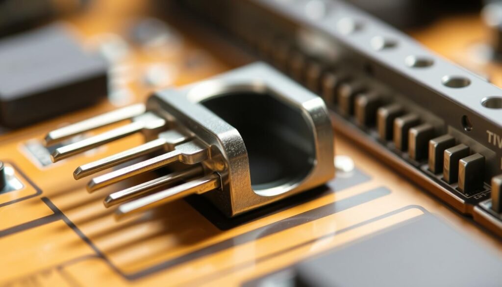
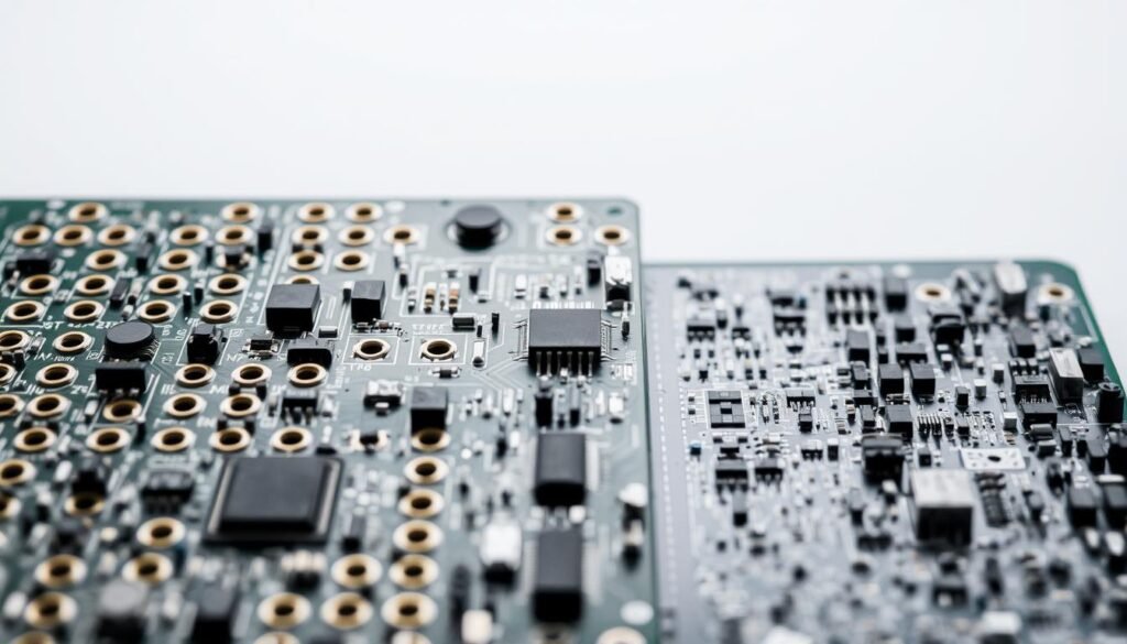
In an age dominated by surface-mount miniaturization, many assume older assembly techniques belong in museums. Yet components requiring extreme durability—like aerospace systems or industrial machinery—rely on a proven approach that predates the microchip. Why would engineers choose a method developed when vacuum tubes ruled electronics?
The answer lies in unmatched mechanical stability. While modern alternatives excel at space efficiency, inserting leads through drilled PCB holes creates bonds that withstand vibration, heat stress, and repeated adjustments. This makes it ideal for prototypes needing frequent modifications.
We’ve seen automotive manufacturers combine surface-mount efficiency with strategic through-hole placements for critical sensors. Medical device designers similarly use it for high-voltage power supplies where failure isn’t an option. The technique’s longevity stems from solving problems newer technologies can’t address.
Key Takeaways
- Decades-old assembly methods remain vital for extreme durability requirements
- Mechanical strength outperforms surface-mount in high-stress environments
- Preferred for prototyping due to easier manual adjustments
- Coexists with modern techniques in hybrid manufacturing strategies
- Critical for applications demanding field serviceability
- Maintains relevance through specialized industrial and military uses
Overview of Through-Hole Technology in PCB Assembly
While modern electronics prioritize compact designs, certain manufacturing principles from the 1940s continue shaping today’s robust systems. This method’s staying power stems from its unique fusion of reliability and adaptability across decades of technological change.
From Vacuum Tubes to Multilayer Boards
The origins of lead-through construction coincide with World War II’s radar systems. Early technicians hand-drilled phenolic boards, creating pathways for components that powered military communications. A 1951 engineering journal notes: “Component leads passing through substrate layers represent the most stable interconnection method yet devised.”
Three key developments transformed this approach:
| Era | Innovation | Impact |
|---|---|---|
| 1940s | Single-sided boards | Enabled mass-produced radios |
| 1960s | Double-sided plating | Doubled circuit density |
| 1980s | Automated insertion | Cut assembly time by 70% |
Core Mechanics of Lead-Based Assembly
Modern PCB assembly services still employ this method for components requiring physical anchoring. The process involves:
- Precision drilling of board substrates
- Insertion of component leads through cavities
- Wave soldering for permanent bonds
Essential parts using this approach include high-wattage resistors and electrolytic capacitors. These elements benefit from the enhanced heat dissipation provided by through-board mounting, particularly in power regulation circuits.
Why Engineers Trust Time-Tested Connection Methods

In sectors where failure isn’t an option, certain connection strategies maintain dominance despite newer alternatives. We see this daily in aerospace control systems and medical monitoring equipment – environments demanding absolute certainty in every electrical joint.
Unshakable Bonds for Critical Systems
Metal leads penetrating circuit boards create multi-point anchors that surface mounts can’t match. These connections withstand 3x more mechanical stress than typical SMT joints according to IPC-610 standards. The secret lies in solder wicking through plated holes, forming conical fillets that lock components in place.
High-power applications particularly benefit from this approach. Larger lead diameters handle up to 20A continuous current, while the through-board design dissipates heat 40% more effectively than surface-mounted equivalents. This makes them essential for industrial motor drivers and renewable energy inverters.
Design Flexibility During Development Phases
Prototyping becomes significantly easier when using components you can physically manipulate. Our engineers often start with leaded parts during initial testing – the visible connections allow quick circuit modifications using basic tools. “You can’t probe what you can’t see,” notes senior designer Mark Tabor from BAE Systems.
Field repairs follow similar logic. When a marine navigation system fails at sea, technicians need solutions that don’t require microscopic soldering stations. Through-board components enable component-level fixes with standard equipment, keeping critical systems operational worldwide.
Disadvantages and Limitations of Through-Hole Assembly

Every manufacturing approach carries inherent compromises. While lead-through methods excel in durability, they introduce specific challenges that designers must navigate in space-constrained applications.
Space Constraints in Modern Electronics
Leaded components demand 3-5x more board area than surface-mount equivalents. This impacts component density, particularly in wearables and IoT devices where every millimeter counts. Multi-layer designs face additional hurdles – through-holes occupy vertical space that could otherwise host signal layers.
Drilling requirements compound these issues. A typical 10cm² board with 200 holes adds 15% to fabrication time versus SMT-ready designs. Each cavity weakens the substrate slightly, requiring careful stress analysis in high-vibration environments.
Economic Realities of Traditional Assembly
Labor costs dominate production budgets for lead-based boards. Manual insertion and trimming account for 40-60% of assembly time in mixed-technology PCBs. While automated systems exist, they struggle with component variety – a key reason military contractors maintain specialized insertion teams.
Wave soldering presents another cost factor. This process consumes 30% more energy than reflow ovens per board, according to IPC-7531 guidelines. For batches under 500 units, these expenses often outweigh the method’s reliability benefits.
We recommend strategic hybrid designs. Place high-stress components using leaded mounting while employing SMT for dense logic sections. This balances durability with manufacturing efficiency, particularly in automotive control modules and power supply units.
Key Applications and Use Cases for Through-Hole Technology
Certain industries demand connection methods that laugh at failure. From vibrating engine compartments to sterile operating rooms, components must perform flawlessly under punishing conditions. This is where lead-based mounting shines, anchoring critical systems across sectors where risk tolerance approaches zero.
Automotive, Industrial, and Healthcare Environments
Automotive engineers specify through-hole parts for systems that battle daily abuse. Engine control modules use them for temperature sensors that endure -40°F cold starts. Anti-lock braking systems rely on their vibration resistance during sudden stops. Infotainment systems benefit too—dashboard displays survive pothole impacts thanks to secure solder joints.
Medical device makers face higher stakes. Patient monitors using these components maintain stable readings during ambulance transport. EKG machines leverage their durability for repeated probe connections. As one Boston Scientific engineer told us: “We can’t have leads shaking loose during open-heart surgery.”
| Industry | Application | Key Benefit |
|---|---|---|
| Automotive | ABS Controllers | Vibration Resistance |
| Healthcare | Infusion Pumps | Zero Downtime |
| Industrial | Motor Drives | Heat Dissipation |
| Energy | Solar Inverters | High Current Capacity |
Use in Heavy-Duty and High-Power Circuits
Industrial settings showcase these components’ muscle. Programmable Logic Controllers (PLCs) use them for power stages handling 480VAC. Lead-based components in motor drives survive years of electrical noise and dust storms. Their secret? Robust thermal management that prevents meltdowns during 24/7 operation.
High-wattage applications demand physical heft. Power supplies for MRI machines use through-board resistors that handle 25A continuous loads. Amplification circuits in broadcast equipment rely on their ability to dissipate 150W+ without failing. When every connection counts, engineers still choose this battle-tested approach.
Through-Hole (THT) Assembly: When is this Technology Still Necessary?
Not all electronic bonds thrive in the age of microscopic components. Designers face critical decisions when balancing modern efficiency against proven reliability. We’ll explore where traditional methods maintain irreplaceable value in contemporary manufacturing.
Head-to-Head: Two Approaches, Different Strengths
SMT dominates high-volume production with rapid pick-and-place automation and reflow soldering precision. However, our analysis reveals where lead-through mounting excels:
| Factor | SMT Advantage | THT Advantage |
|---|---|---|
| Assembly Speed | 15,000 components/hour | Manual prototyping flexibility |
| Power Handling | Up to 5A per component | 20A+ continuous current |
| Environmental Resistance | -40°C to 125°C | Withstands thermal shock cycles |
| Field Repairability | Requires micro-soldering | Toolkit-friendly maintenance |
Wave soldering in lead-based assembly creates joints that survive decades of vibration. This makes it essential for industrial motor controllers and power grid monitoring systems.
Non-Negotiable Applications
Three sectors consistently require this approach:
- Aerospace: Flight control systems needing 25-year lifespans
- Medical: Defibrillators requiring instant response after years of storage
- Energy: Solar farm inverters facing daily thermal cycling
As detailed in our comprehensive guide to lead-based PCB assembly, the choice ultimately depends on operational demands rather than trends. Hybrid designs often yield optimal results – using SMT for signal processing while anchoring power stages through-board.
Practical Considerations for PCB Designers and Manufacturers
Mastering component integration requires balancing cutting-edge techniques with proven mechanical principles. We guide engineers through critical decisions that determine product longevity and performance.
Precision Engineering for Reliable Connections
Hole sizing errors account for 23% of manufacturing defects according to IPC-2221 standards. Our design rules prevent common pitfalls:
| Design Factor | Specification | Impact |
|---|---|---|
| Hole Diameter | Lead size + 0.15mm | Ensures proper solder wicking |
| Spacing | 2x hole diameter | Prevents thermal bridging |
| Edge Placement | 5mm from board edge | Enhances mechanical stability |
Strategic component positioning reduces stress concentrations. Place heavy transformers near mounting points using three-point support configurations. This distributes forces evenly across the substrate.
Wave soldering effectiveness depends on access patterns. Design boards with all leads exiting the same side to prevent shadow effects. Our team achieves 99.8% first-pass yield using this approach in power supply units.
Plated through-holes remain non-negotiable for harsh environments. Specify ENIG (Electroless Nickel Immersion Gold) finishes when operating in humid conditions. This combination prevents oxidation while maintaining solderability for field repairs.
“Proper design eliminates 80% of potential failure points before manufacturing begins.”
Implement these strategies to create boards that withstand decades of service. Remember: every design choice impacts manufacturability, serviceability, and ultimate reliability.
Conclusion
Innovation drives electronics forward, but true reliability often comes from battle-tested solutions. For critical systems demanding uncompromising durability, through-hole components remain indispensable. Their physical anchoring outperforms surface-mount alternatives in extreme conditions—whether stabilizing flight controls at 30,000 feet or ensuring medical devices survive decades of use.
We continue specifying these components where mechanical stability and thermal performance define success. Industries from aerospace to energy infrastructure rely on their proven track record, as detailed in our analysis of durability-focused assembly methods. The combination of visible joints and robust solder bonds addresses challenges modern miniaturization can’t solve alone.
Forward-thinking designs now blend legacy strengths with contemporary efficiency. By using strategic DIP configurations alongside SMT density, engineers achieve optimal performance without sacrificing serviceability. As technology evolves, some foundations remain timeless—especially when failure isn’t an option.
FAQ
How does wave soldering differ from reflow processes in PCB manufacturing?
Why do some industries still prefer DIP packages over modern alternatives?
Can designers mix through-hole and surface-mount components effectively?
What cost factors make THT less economical for high-volume production?
Which components typically demand through-hole mounting today?
How do IPC standards impact through-hole assembly quality?
About The Author
Elena Tang
Hi, I’m Elena Tang, founder of ESPCBA. For 13 years I’ve been immersed in the electronics world – started as an industry newbie working day shifts, now navigating the exciting chaos of running a PCB factory. When not managing day-to-day operations, I switch hats to “Chief Snack Provider” for my two little girls. Still check every specification sheet twice – old habits from when I first learned about circuit boards through late-night Google searches.
