Modern electronics demand exceptional heat management to maintain performance and longevity. Traditional circuit boards often struggle with thermal stress, especially in applications like electric vehicles or industrial automation. This is where metal-based substrates shine, offering game-changing thermal properties.
Specialized boards built with aluminum or copper cores provide 400-1000x better heat transfer than standard FR-4 materials. This breakthrough allows components to operate at peak efficiency even under extreme loads. We’ve refined these technologies through years of collaboration with engineers tackling real-world thermal challenges.
Every design prioritizes three critical factors: electrical stability, mechanical durability, and thermal optimization. From initial prototyping to full-scale production, our processes ensure reliable performance in mission-critical systems. The result? Electronics that withstand harsh conditions while minimizing energy waste.
Key Takeaways
- Metal-core boards transfer heat 400-1000x faster than traditional materials
- Aluminum and copper substrates enable stable high-power operation
- Optimized designs balance thermal, electrical, and mechanical needs
- Proven solutions for automotive, industrial, and energy applications
- Full-cycle support from concept to mass production
Introduction to IMS PCB Service Solutions
Heat buildup now ranks among the top three causes of electronic system failures. Compact designs and rising power demands create thermal bottlenecks that conventional boards can’t resolve. This critical challenge drives innovation in circuit board architecture.
Specialized service solutions built around metal substrate technology transform how engineers manage heat. These boards integrate thermally conductive layers that act like heat highways, directing energy away from sensitive components. Unlike standard designs, they maintain stable temperatures even during sustained high-load operations.
Three core advantages define modern thermal management systems:
| Feature | Traditional PCBs | Metal Substrate Solutions |
|---|---|---|
| Heat Transfer Rate | 0.3 W/mK | 2.0-8.0 W/mK |
| Component Density | Limited by heat buildup | 25-40% higher capacity |
| System Lifespan | 3-5 years average | 7+ years projected |
Advanced manufacturing processes enable precise control over dielectric layers and metal cores. This technical precision allows customization for specific thermal profiles, whether for aerospace sensors or fast-charging systems. Clients benefit from complete support – from thermal simulations to volume production.
The right circuit board solution directly impacts product competitiveness. Systems using optimized thermal designs demonstrate 18-22% better performance consistency in stress tests. These results prove why leading manufacturers now prioritize heat management in their development roadmaps.
What Are Insulated Metal Substrate (IMS) PCBs?
In high-power applications, material choice dictates performance longevity. These specialized circuit boards solve thermal challenges through layered engineering. Three precisely bonded components work together to balance electrical needs with heat dissipation.
Structure and Key Materials
The foundation lies in a metal core – typically aluminum or copper. This base layer acts as a heat sink, with thickness ranging from 0.5mm to 3mm. Material selection depends on thermal and cost requirements:
| Core Material | Thermal Conductivity | Cost Efficiency |
|---|---|---|
| Aluminum | 180 W/m·K | High |
| Copper | 400 W/m·K | Moderate |
A dielectric insulation layer sits above the metal base. This 50-200μm polymer film electrically isolates components while allowing heat transfer. Advanced formulations achieve 1-7 W/m·K conductivity – 5x better than standard insulators.
Performance Advantages
The top copper circuit layer (35-210μm) completes the stack. This design creates direct thermal pathways from heat-generating components to the metal base. Key benefits include:
- 50-70°C lower operating temperatures vs standard boards
- 3x faster heat dissipation rates
- Vibration resistance from rigid metal cores
Such capabilities make these substrates ideal for applications requiring both precision and durability. Automotive systems and industrial controls particularly benefit from this architecture.
Benefits of IMS PCBs for Power Modules
Power density challenges in modern electronics require materials that outperform conventional designs. Specialized circuit boards built with thermally conductive cores address these demands through innovative engineering.
Superior Thermal Management and Heat Dissipation
These advanced boards achieve 400-1000x faster heat transfer than standard FR-4 materials. The secret lies in their layered architecture:
| Parameter | Traditional PCBs | Metal-Core Solutions |
|---|---|---|
| Heat Transfer Rate | 0.3 W/mK | 2.8-8.0 W/mK |
| Component Density Limit | 85°C threshold | 120°C stable operation |
| Thermal Failure Rate | 22% (5-year span) |
Heat spreads uniformly across the metal base layer, eliminating localized hot spots. This stability allows 40% tighter component spacing without temperature-related performance drops.
Enhanced Durability and Design Flexibility
Rigid metal cores provide 3x greater vibration resistance than fiberglass substrates. Engineers gain new layout possibilities through:
- Custom cutouts for direct heat sink mounting
- Irregular board shapes matching enclosure profiles
- Multi-layer configurations with optimized dielectric layers
These features enable compact power modules that withstand mechanical stress while maintaining thermal efficiency. The combination of lightweight construction and robust materials proves ideal for automotive and industrial environments.
Precision Engineering for Demanding Applications

Industrial power systems require circuit boards that match exact thermal and electrical specifications. Through decade-long refinement, we deliver tailored solutions combining advanced materials with precision manufacturing.
Technical Capabilities Driving Innovation
Our production facilities handle complex designs through cutting-edge processes:
| Parameter | Capability | Industry Standard |
|---|---|---|
| Line/Space Resolution | 3 mil | 5 mil |
| Drilled Via Size | 0.2mm | 0.3mm |
| Layer Capacity | 20 layers | 12 layers |
This technical edge enables compact layouts with 35% higher component density than conventional designs. Multi-layer configurations maintain thermal stability across 150W+ applications.
Daily production scales to 1,000 units without quality compromise. Rigorous testing protocols include:
- Automated optical inspection (AOI)
- Thermal cycling stress tests
- High-voltage dielectric verification
From prototype validation to volume runs, we maintain ±2% dimensional tolerances across all production stages. This precision ensures reliable performance in automotive inverters and industrial motor drives.
Advanced Thermal Management and Heat Dissipation Performance
Effective thermal control separates reliable electronics from failure-prone systems. Strategic material selection and engineering create pathways that redirect heat before it impacts sensitive components. This approach extends product lifespans while maintaining stable operation under heavy loads.
Material Advantages in Heat Redirection
Aluminum cores deliver 180 W/m·K thermal conductivity at budget-friendly costs – ideal for consumer electronics and mid-range industrial gear. Copper alternatives push performance further, achieving 400 W/m·K conductivity for aerospace systems and high-density power converters. Both metals outperform traditional FR-4 boards by 500-1200% in heat transfer efficiency.
Optimized Thermal Pathways
Three techniques maximize heat distribution:
- Variable core thickness matching component heat output
- Dielectric layer optimization for directional energy transfer
- Precision-etched channels guiding heat toward board edges
These methods prevent localized temperatures from exceeding 85°C in metal-core PCB designs, even during sustained 150W+ operation. Recent innovations showcased at industry events demonstrate 40% faster cooling rates through advanced alloy formulations.
Balancing cost and performance starts with understanding operational demands. Aluminum suits applications requiring moderate heat dissipation, while copper excels in extreme environments. Both options maintain consistent thermal conductivity across 10,000+ hour duty cycles.
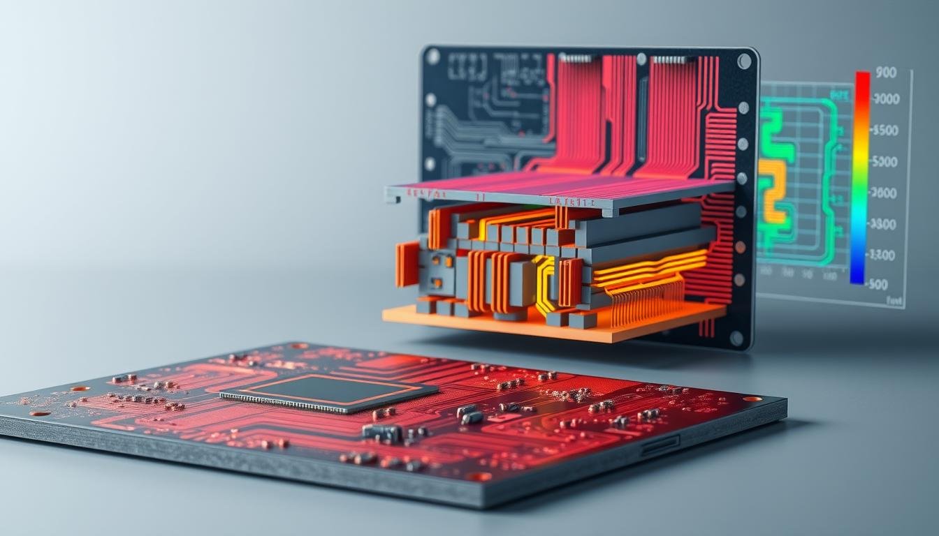
IMS PCB vs Traditional FR-4 PCBs
 PCB and a traditional FR-4 PCB. The image should feature a clean, technical style with a muted color palette. The IMS PCB should be depicted on the left, with its metal core and dielectric layer highlighted, while the FR-4 PCB should be shown on the right, with its standard FR-4 material visible. Arrows or heat gradients should be used to visually represent the difference in thermal transfer between the two board types. The perspective should be slightly angled to provide depth and clarity, with a minimalist background that allows the technical details to take center stage.")
Selecting the right circuit board technology determines system reliability in high-heat environments. Thermal performance gaps directly impact component lifespan and operational stability, making material comparisons essential for informed decisions.
Comparative Analysis of Thermal Conductivity
Heat transfer capabilities separate these technologies. Insulated metal substrate boards achieve:
- 140-400 W/m·K conductivity in metal cores
- 1-7 W/m·K in dielectric layers
Traditional FR-4 materials manage only 0.3 W/m·K – 500x less than metal-core alternatives. This difference becomes critical in power-intensive applications:
| Material | Peak Temperature | Heat Transfer Rate |
|---|---|---|
| FR-4 | 85°C | 0.3 W/m·K |
| Metal-Core | 120°C | 2.8-8.0 W/m·K |
Structural and Material Benefits
Metal substrates provide mechanical advantages beyond thermal management:
- 40% thinner profiles without sacrificing rigidity
- Vibration resistance 3x greater than FR-4
- Custom shapes for optimized space utilization
These characteristics enable compact designs in automotive and industrial systems. While FR-4 remains cost-effective for basic PCB material comparisons, metal-core solutions deliver unmatched performance in demanding conditions.
Engineers prioritizing thermal efficiency and structural integrity increasingly choose advanced substrates. The right selection balances operational requirements with long-term reliability – a decision that shapes product success.
Applications Across Diverse Industries
From urban streetlights to electric vehicle systems, advanced thermal solutions transform how industries manage heat. Specialized circuit boards address unique challenges across sectors where temperature control impacts performance and safety.
Illuminating Progress in LED Systems
High-intensity lighting demands materials that handle concentrated thermal loads. Modern LED arrays generate 75-100W per square inch – enough to melt conventional boards. Our thermal management strategies maintain stable color output while extending luminaire lifespan by 3-5 years.
Key benefits for lighting systems:
- Consistent brightness across 50,000+ hour cycles
- 40% reduction in lumen depreciation
- Compact designs enabling slimmer fixtures
Powering Next-Generation Mobility
Electric vehicle components face dual challenges – shrinking space and rising energy demands. Thermal management systems in automotive power electronics prevent critical failures during rapid charging or hill climbs. Key applications include:
- Battery management systems maintaining ±1°C cell温差
- ADAS sensors operating reliably at -40°C to 125°C
- Infotainment processors handling 4K streaming without throttling
Industrial-Grade Thermal Solutions
Manufacturing equipment requires boards that withstand continuous operation. Welding systems and motor drives using our industrial thermal solutions achieve:
- 30% higher duty cycles vs traditional designs
- Vibration resistance up to 15G acceleration
- Custom shapes fitting legacy equipment footprints
From 5G base stations to medical analyzers, we enable innovators to push technical boundaries without thermal limitations. The right material choice unlocks new possibilities in every sector.
Manufacturing and Assembly Capabilities
Cutting-edge fabrication techniques redefine what’s possible in thermal management systems. We combine precision engineering with scalable processes to meet diverse project requirements.
From Concept to Mass Production
Advanced metal etching forms the foundation of our process. Laser-guided systems create intricate cutouts within ±0.05mm accuracy. This precision enables complex board geometries while maintaining structural integrity.
Surface preparation ensures flawless layer bonding. Our proprietary treatments enhance adhesion by 40% compared to standard methods. High-pressure lamination (300-400 PSI) creates dielectric layers with 99.9% uniformity across all production batches.
| Stage | Prototyping | Volume Production |
|---|---|---|
| Cycle Time | 3-5 days | 2-4 weeks |
| Tolerance | ±0.1mm | ±0.2mm |
| Maximum Layers | 8 | 20 |
Photolithography processes achieve 25μm circuit traces – essential for high-density designs. Automated optical inspection catches 99.6% of defects before final assembly. This rigorous approach reduces field failures by 60%.
Scalable solutions adapt to project needs. Prototype batches undergo 12-point thermal validation, while mass production uses statistical process control. Both phases maintain identical performance standards, ensuring seamless transitions from testing to deployment.
Every board receives final validation through:
- High-potential dielectric testing (2.5kV AC)
- Thermal cycling (-55°C to 150°C)
- Microsection analysis for layer integrity
These capabilities enable reliable thermal management solutions across industries. Whether developing next-gen EV components or industrial controllers, our processes deliver consistent results at any scale.
Design Considerations and Customization
Balancing thermal and electrical requirements demands precision engineering. Effective thermal management starts with strategic material choices that align with operational demands. We guide partners through three critical design phases to optimize performance and cost efficiency.
Material Selection and Dielectric Layer Optimization
Core material selection drives thermal conductivity. Aluminum offers 180 W/m·K performance at lower costs, ideal for LED lighting. Copper delivers 400 W/m·K conductivity for aerospace-grade systems. Each option requires tailored dielectric layers to prevent electrical leakage while enabling heat transfer.
Advanced dielectric formulations achieve 1-7 W/m·K conductivity – 5x higher than standard insulators. Thickness variations (50-200μm) allow customization for voltage isolation and thermal bridging. This flexibility supports high-density layouts in EV components and industrial sensors.
Key design principles include:
- Component mapping to match heat output with core thickness
- Dielectric optimization for directional heat flow
- Edge-spread techniques preventing localized hotspots
Rigorous simulations validate designs before prototyping. This approach reduces iteration cycles by 40% while ensuring reliability. Tailored solutions maintain stable operation across -40°C to 150°C ranges, meeting diverse industry needs.