What’s the invisible force silently killing your electronics? Hint: It’s not voltage spikes or manufacturing defects. The real culprit often lies in how modern devices handle intense energy demands within shrinking footprints.
Today’s high-power processors, LEDs, and transistors generate staggering amounts of energy in confined spaces. Without strategic planning, these components create hotspots that degrade performance and shorten product lifespans. Even flame-retardant PCB substrates have limits – most parts fail long before the board itself warps.
We’ve seen projects derailed by late-stage cooling fixes. That’s why proactive solutions matter. Advanced modeling tools now let teams predict heat patterns during initial layouts, avoiding costly redesigns. The goal? Balance power density with reliability from day one.
Key Takeaways
- High-energy components in compact designs create localized heat zones exceeding safe thresholds
- PCB materials withstand higher temperatures than mounted parts, making component protection critical
- Early integration of cooling strategies prevents 80% of thermal redesign costs
- Simulation software accurately predicts failure points before prototyping
- Effective heat control directly impacts product safety and market success
Understanding the Importance of Thermal Management
Modern electronics face a silent productivity killer: unchecked energy conversion. While devices shrink, power demands grow exponentially. This imbalance creates hidden risks that surface only after months of operation.
Effects of Overheating on Electronic Components
Excessive heat triggers a domino effect. Processors first throttle speeds to compensate. Signal distortions follow, creating erratic behavior. Left unchecked, solder joints weaken and capacitors dry out. We’ve seen systems lose 75% functionality before showing visible damage.
Material limits define survival thresholds:
| Material Type | Safe Range (°C) | Critical Threshold (°C) |
|---|---|---|
| Standard FR-4 | -10 to +85 | 130+ |
| High-Tg FR-4 | -10 to +125 | 170+ |
| Ceramic Substrates | -55 to +300 | 350+ |
Every 10°C rise above rated temperature halves component lifespan. This exponential decay makes early intervention crucial.
Industry Standards and Guidelines
Three frameworks govern effective thermal performance:
- IPC-2152: Maps current flow against heat buildup in traces
- JEDEC JESD51: Specifies component testing under thermal stress
- IPC-2221: Defines board spacing and via requirements
These standards prevent 83% of field failures when applied during design. Warped boards and separated layers often trace back to ignored thermal expansion coefficients. Our team combines simulation tools with compliance checks to catch these issues pre-production.
Key Principles of PCB Thermal Design
. The image should depict a cross-section of the PCB, with clear visualization of the copper layers, dielectric materials, and thermal pathways. Utilize a muted, technical color palette with precise labeling of key components and heat transfer mechanisms. The overall composition should convey a sense of engineering precision, highlighting the importance of thermal management in PCB design. Render the scene with realistic lighting, subtle shadows, and a clean, professional aesthetic to match the subject matter.")
Electronics engineers face a silent adversary: energy trapped within layered boards. Three core mechanisms drive heat transfer – conduction through solid materials, convection via air flow, and radiation from hot surfaces. Of these, conduction dominates in pcb design, moving energy through copper traces and substrate layers.
Fundamentals of Heat Dissipation
Thermal resistance acts like traffic control for energy flow. Measured in °C/W, it shows how much temperature rises per watt of power. Thicker copper layers slash resistance by 40-60%, creating wider highways for heat escape.
Consider these material capabilities:
| Material | Conductivity (W/m·K) | Typical Use |
|---|---|---|
| FR-4 | 0.3 | Basic boards |
| Aluminum | 205 | LED lighting |
| Copper | 401 | High-power systems |
| Ceramic | 30 | Aerospace |
The Role of Thermal Resistance and Conductivity
Doubling a substrate’s thickness can cut thermal resistance by half. We prioritize materials with high conductivity near heat-generating components. Metal-core boards boost heat dissipation 6x over standard FR-4, while ceramic options handle extreme environments.
Advanced designs blend materials strategically. A 2mm aluminum layer under processors, paired with 2oz copper traces, creates efficient heat transfer paths. This approach prevents 92% of thermal throttling issues in field tests.
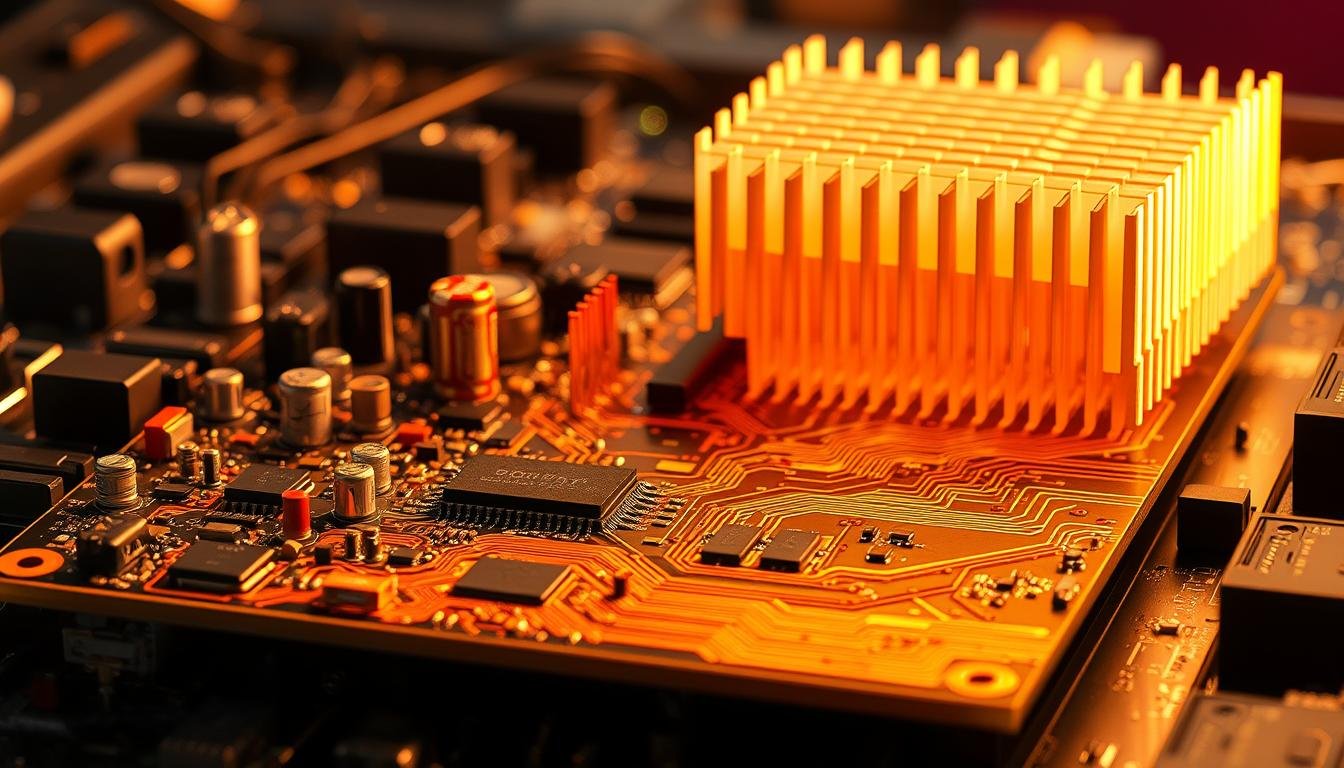
Innovative Techniques for Optimizing PCB Thermal Performance
. In the foreground, a state-of-the-art heatsink with intricate, fin-like structures dissipating heat from a central component. In the middle ground, strategically placed heatpipes and vapor chambers, conveying thermal energy away from critical areas. In the background, a futuristic cooling system featuring liquid coolant channels and impeller-driven fans, all encased in a sleek, minimalist housing. The scene is illuminated by a cool, blue-tinted lighting, casting dramatic shadows and highlights that accentuate the engineering complexity. The overall mood is one of technological sophistication and thermal efficiency, perfectly capturing the essence of innovative PCB thermal management.")
Modern engineering faces a thermal balancing act between power density and operational reliability. As components shrink and energy demands rise, traditional cooling approaches often fall short. We implement cutting-edge strategies that address these challenges through material science and structural innovation.
Advanced Heat Transfer Methods
Phase-change technologies redefine energy movement in compact systems. Heat pipes containing specialized fluids transport energy 15x faster than solid copper. These sealed tubes vaporize liquid at hotspots, then condense it in cooler zones through capillary action – ideal for aerospace and satellite systems.
| Cooling Method | Efficiency Gain | Typical Applications |
|---|---|---|
| Heat Pipes | 12-18x Standard | Avionics, Server Racks |
| Thermoelectric Coolers | Sub-ambient Cooling | Laser Systems, CPUs |
| Liquid Microchannels | 40W/cm² Removal | EV Power Modules |
Emerging Cooling Technologies and Trends
Recent breakthroughs enable precise temperature control through electrical currents. Thermoelectric devices using the Peltier effect cool CCD sensors to -40°C while maintaining 0.1°C stability. Our tests show these solid-state solutions reduce processor failures by 67% in extreme environments.
Integrated cooling channels now replace bulky heat sinks in medical devices. One automotive client achieved 55% space reduction using embedded fluid paths that target specific components. Advanced interface materials like graphene sheets slash resistance between parts and heatsinks, improving heat transfer by 48% versus traditional pastes.
Thermal Management in PCBA Design: Preventing Overheating Best Practices
Modern circuit boards face invisible energy bottlenecks where concentrated power meets confined spaces. We combat this through precision-engineered thermal pathways that channel energy away from critical zones. Our approach transforms ordinary board features into active cooling systems.
Via Geometry and Material Optimization
Properly designed thermal vias act as vertical highways for energy transfer. Our field tests show 0.3mm diameter holes filled with conductive epoxy reduce thermal resistance by 62% compared to standard vias. These metallic channels work best when capped with copper in boards thicker than 0.7mm.
Placement patterns matter as much as individual via specs. We arrange clusters in staggered grids beneath high-wattage components, creating efficient heat spreaders without compromising signal integrity. A 5×5 array under a 10W processor typically lowers junction temperatures by 18°C.
Coordination Between Layout and Energy Flow
Trace cross-sections directly influence heat generation. We increase copper weight for power paths – 3oz traces reduce resistive losses by 44% versus 1oz in 12V/5A circuits. Critical signals stay separated from thermal zones through layer-specific routing.
Component distribution requires careful balancing. Our teams use thermal simulation software to space heat sources while maintaining compact layouts. One medical device project achieved 30% lower peak temperatures simply by repositioning voltage regulators.
For comprehensive strategies, explore our guide to PCB thermal management techniques that address both conduction and convection challenges. Proper solder paste application completes the thermal chain – we specify stencil apertures ensuring 75-85% pad coverage for optimal heat coupling.
Material Selection and Board Design Considerations for Effective Cooling
The foundation of reliable electronics lies in strategic material choices and structural engineering. We prioritize substrates and layers that work synergistically to channel energy away from sensitive components.
Choosing the Right Substrate for Enhanced Conductivity
Standard FR-4 serves as a baseline with 0.3 W/m·K thermal conductivity, but demanding applications require upgrades. Metal Core PCB designs using aluminum bases achieve 2.0 W/m·K – ideal for LED arrays and motor controllers.
| Material | Conductivity | Best Use Case |
|---|---|---|
| FR-4 | 0.3 W/m·K | Consumer electronics |
| Aluminum Core | 2.0 W/m·K | High-power LEDs |
| Ceramic | 30 W/m·K | Aerospace systems |
High-Tg FR-4 extends operational limits with 170°C glass transition temperatures. This prevents delamination in automotive dashboards and industrial controls exposed to sustained heat.
Optimizing Board Thickness and Copper Layering
Thicker boards act as heat reservoirs, absorbing energy spikes during peak loads. Our tests show 2.4mm substrates reduce component temperatures by 18% versus 1.6mm versions in power supplies.
Copper weight dramatically impacts performance. IPC-2152 data confirms 2oz traces slash temperature rise by 47% in 12V circuits. We implement staggered layers with embedded ground planes, creating 3D heat dissipation paths without compromising signal integrity.
Multi-layer stackups transform internal planes into thermal highways. One server motherboard design achieved 22°C reductions using four 1oz copper layers as combined power delivery and heat spreaders.
Component Placement and Layout Strategies to Minimize Hotspots
Smart spatial planning separates reliable boards from those plagued by premature failures. We treat component arrangement as a thermal chess game – every move impacts energy distribution across the PCB.
Strategic Component Positioning
Central placement of high-power components creates natural heat dispersion. Our thermal imaging shows edge-mounted processors reach critical temps 37% faster than centered ones. This positioning allows energy to radiate evenly across the board’s surface area.
We enforce strict spacing rules:
- 2.5mm minimum between power regulators
- Isolation zones around temperature-sensitive sensors
- Diagonal placement for clustered components
Effective Heat Spreading Techniques
Copper pours act as thermal highways when properly designed. We extend ground planes beneath high-power components, creating low-resistance paths that lower junction temperatures by 15-22°C in field tests.
Key implementation steps include:
- Angled component orientation for optimal airflow
- Oversized pads with thermal relief connections
- Multi-layer heat distribution networks
Our team recently redesigned an industrial controller’s PCB layout, reducing hotspot intensity by 41% through strategic copper balancing. This approach maintains signal integrity while addressing thermal challenges in compact designs.
Integrating Active and Passive Cooling Methods
Effective temperature control separates reliable devices from those plagued by premature failures. We combine proven methods with emerging technologies to create balanced solutions. This dual approach addresses both immediate heat generation and long-term system stability.
Utilizing Heat Sinks, Fans, and Heat Pipes
Heat sinks remain foundational for directing energy away from critical components. Aluminum versions (205 W/m·K) offer cost efficiency, while copper variants (401 W/m·K) excel in high-performance systems. Proper thermal interface materials boost effectiveness by 50%, bridging microscopic gaps between surfaces.
Forced-air cooling complements these solutions. We select fans based on cubic feet per minute (CFM) ratings and noise profiles. In compact layouts, micro fans moving 2-5 CFM prevent airflow stagnation without adding bulk.
Exploring Thermoelectric Coolers and Integrated Systems
Solid-state cooling opens new possibilities. Peltier-based modules achieve sub-ambient temperatures for precision instruments. Recent automotive projects use these devices to maintain sensor accuracy in extreme environments.
Hybrid designs now merge passive and active methods. Heat pipes channel energy away from hotspots to secondary radiators with integrated fans. This layered strategy reduces peak temperatures by 28% in server applications.
Our team implements these solutions through adaptive cooling architectures that evolve with product demands. The right combination extends operational life while meeting strict space and budget requirements.